Category Archive Manuals

Bycecelia

ge remote control manual

GE Remote Control Manual: A Comprehensive Guide

This guide offers detailed instructions for GE universal remotes, covering setup, programming, troubleshooting, and advanced features for seamless device control.

GE Universal Remotes are designed to simplify your home entertainment experience by consolidating multiple remote controls into one convenient device. These remotes boast compatibility with a vast array of audio and video equipment, offering users a streamlined control solution. From televisions and DVD players to sound systems and streaming devices, GE remotes aim to provide comprehensive functionality.

Key benefits include ease of use, simplified setup processes, and the ability to control numerous devices with a single unit. Whether you’re seeking a basic replacement or a feature-rich universal controller, GE offers models to suit diverse needs. This manual will guide you through the process of maximizing your GE remote’s potential.

Understanding GE Remote Control Models

GE offers a diverse range of universal remote control models, each catering to specific user preferences and device compatibility needs. Popular models include the 33701 Big Button Remote, designed for simplicity and ease of use, particularly for seniors. The 33709, 33710, and 33711 series provide broader device support and additional features.

More advanced options like the RM24918 and RM84918 offer enhanced programming capabilities and compatibility with newer devices. Understanding the model number is crucial for accessing the correct code list and specific instructions. Each model’s manual details its unique features and supported devices, ensuring optimal performance and a tailored user experience.

Setting Up Your GE Remote

Initial setup involves installing batteries and verifying device compatibility before proceeding with programming, ensuring a smooth and functional remote experience.

Initial Battery Installation

To begin, locate the battery compartment, typically on the back or bottom of the remote. Gently slide open the compartment cover, often requiring a small amount of pressure or a designated release button. Insert the required batteries – usually AAA or AA – ensuring correct polarity, as indicated by the “+” and “-” symbols inside the compartment.

Incorrect battery placement can prevent the remote from functioning. Once the batteries are securely in place, close the compartment cover until it clicks shut. A properly installed battery ensures the remote powers on and is ready for the programming process. Always use fresh batteries for optimal performance and avoid mixing old and new batteries.

Device Compatibility Check

Before programming, verify your devices are compatible with the GE universal remote. Most modern televisions, DVD players, Blu-ray players, and audio systems are supported, but older or less common brands might require checking the GE remote code list. This list, available online or within the manual, details supported manufacturers and model numbers.

Confirming compatibility prevents frustration during setup. If your device isn’t listed, the remote may not function correctly. Some remotes support learning functionality, allowing you to copy signals from your original remote, offering a workaround for unsupported devices. Always consult the code list first to ensure a smooth programming experience.

Programming Your GE Remote

Effectively control your devices using direct code entry, auto code search, or the GE remote code list – methods detailed for easy setup and operation.

Direct Code Entry Method

The direct code entry method allows precise programming of your GE universal remote. First, locate the specific code for your device brand from the GE code list (available online or in the manual). Power on the device you intend to control. Then, press and hold the ‘Setup’ or ‘Magic’ button on the remote until the indicator light turns on.

Enter the five-digit code using the number buttons. The indicator light should blink or turn off, confirming successful code entry. If it doesn’t work, repeat the process, ensuring you’ve selected the correct code for your device’s manufacturer and type. Test the functionality by attempting basic operations like power on/off or volume control.

Auto Code Search Method

The auto code search method is useful when you can’t find a direct code for your device. Begin by powering on the device you wish to control. Press and hold the ‘Setup’ or ‘Magic’ button on your GE remote until the indicator light illuminates. Instead of entering a code, repeatedly press the ‘Power’ button. The remote will sequentially transmit codes to your device.

Watch carefully for your device to respond – typically by powering off or acknowledging the signal. Once a response is detected, immediately press the ‘Enter’ or ‘Stop’ button to lock in the code. Test all functions to confirm complete compatibility. This method can take time, but it’s effective for unsupported devices.

Using the GE Remote Code List

The GE Remote Code List is a comprehensive resource for programming your remote. Locate the code list specific to your remote model – often available online or within the manual itself. Find your device’s brand within the list, then locate the corresponding code(s) provided. Try each code sequentially, as some devices may respond to multiple codes.

To enter a code, press and hold the ‘Setup’ or ‘Magic’ button until the indicator light turns on. Use the number buttons to input the five-digit code, then press ‘Enter’ or ‘Stop’. Test the remote’s functions after each attempt to verify successful programming.

Button Functions and Features

Explore essential buttons like power, volume, and channel controls, alongside input selection and special functions such as menu and information access.

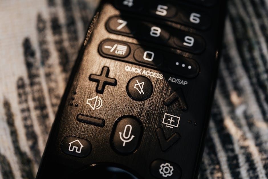
Power, Volume, and Channel Controls

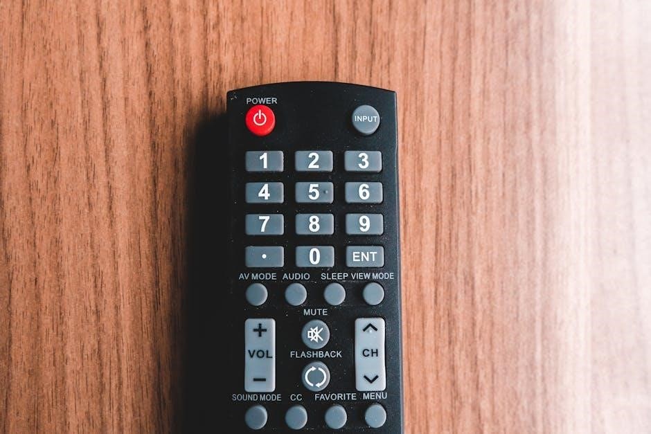
The power button universally controls device on/off functions, offering convenient centralized operation. Volume controls, typically represented by “+” and “-” symbols, adjust audio levels across connected devices. Channel controls, including number buttons and channel up/down, navigate through available channels on your television or set-top box.

These core functions are fundamental to the remote’s usability, providing immediate access to essential viewing adjustments. Some GE remotes feature a mute button for instant audio silencing. Understanding these controls allows for a streamlined entertainment experience, eliminating the need to locate original device remotes. Proper functionality ensures effortless control of your home theater system.

Input Selection and Device Switching

GE universal remotes excel at managing multiple devices, simplifying home entertainment setups. Dedicated input buttons – often labeled “TV,” “DVD,” “AUX,” or “Cable” – allow quick switching between connected sources. The “Device” or “Source” button, combined with number pads, enables selection of specific devices programmed into the remote’s memory.

This feature eliminates the need for multiple remotes, consolidating control into a single unit. Proper configuration ensures the correct input is selected for each device. Some models offer direct access to frequently used inputs, streamlining the viewing experience. Mastering device switching enhances convenience and reduces clutter, creating a more organized entertainment center.

Special Function Buttons (e.g., Menu, Info)

GE universal remotes incorporate specialized buttons for enhanced device control beyond basic operations. The “Menu” button accesses the on-screen menu of the selected device, allowing adjustments to settings like picture, sound, and channel options. The “Info” button displays detailed information about the current program or input source, such as channel number, program title, and runtime.

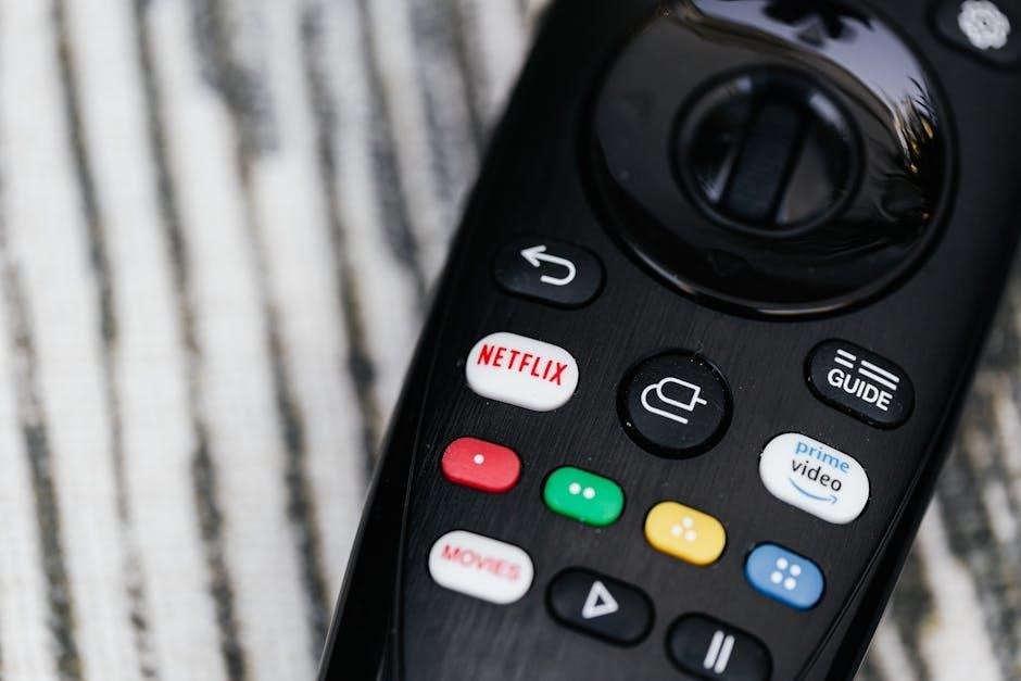
Additional buttons may include “Input,” “Settings,” or dedicated buttons for streaming services. These functions vary depending on the remote model and programmed devices. Understanding these special features unlocks the full potential of your GE remote, providing a more interactive and customized entertainment experience.

Troubleshooting Common Issues

This section addresses frequent problems like unresponsive remotes, programming difficulties, and incorrect code entries, offering solutions for optimal functionality.

Remote Not Responding

If your GE remote isn’t responding, begin with the simplest checks. First, ensure fresh batteries are correctly installed, observing proper polarity; Weak or improperly seated batteries are a common cause. Next, verify there are no obstructions between the remote and the device you’re trying to control; direct line of sight is often necessary.

Try resetting the remote by removing the batteries for several minutes, then reinserting them. If the issue persists, confirm the correct device is selected using the device button. Finally, double-check the programmed code for that device, as an incorrect code will prevent operation. Consider testing with a different device to isolate the problem – is it the remote or the target device?

Difficulty Programming the Remote

Encountering trouble programming your GE remote? Start by ensuring you’re using the correct code for your specific device brand and model. Refer to the GE remote code list – available online or in the manual – and double-check the entered numbers. If using the auto code search, be patient and allow the remote to cycle through all codes.

Ensure the remote is in programming mode, following the manual’s instructions precisely. Sometimes, a weak signal from the device can hinder programming; try moving closer. If problems persist, reset the remote to factory settings and begin the programming process anew. Online code databases can offer alternative codes if the manual’s list fails.

Incorrect Code Entered

If your GE remote isn’t controlling your device properly, an incorrect code is a likely culprit. Symptoms include unresponsive buttons or functions operating erratically. Double-check the code entered against the official GE code list for your device’s brand and model number. Even a single digit error can prevent proper operation.

Try re-entering the code carefully, ensuring each number is registered correctly. If the initial code doesn’t work, consult online code databases as alternative codes may exist. Remember to fully reset the remote before attempting a new code entry. Persistent issues suggest the code list may be outdated or incomplete, requiring further research.

Advanced Features

Explore master volume control and macro programming options (if supported by your GE remote model) for a customized and streamlined entertainment experience.

Master Volume Control

GE universal remotes often feature a Master Volume control, allowing you to adjust the volume of multiple connected devices simultaneously. This eliminates the need to cycle through each device individually to achieve your desired sound level. To utilize this function, ensure your remote is properly programmed for all desired devices – televisions, soundbars, and receivers are common examples.

Typically, you’ll need to configure the remote to recognize which devices are connected to the audio system. Once configured, the Master Volume buttons on the remote will control the volume across all selected devices. This feature greatly simplifies the user experience, particularly in home theater setups with numerous components. Refer to your specific remote model’s manual for detailed setup instructions and customization options related to Master Volume control.

Macro Programming (if applicable)

Certain GE universal remote models support macro programming, a powerful feature enabling you to combine multiple commands into a single button press. This streamlines complex operations, such as powering on several devices, switching inputs, and adjusting volume – all with one touch. Macro functionality isn’t universally available across all GE remotes; check your model’s specifications.

Programming macros usually involves entering a learning mode, then sequentially pressing the buttons representing the desired commands. The remote stores these commands, associating them with a designated macro button. Consult your remote’s manual for precise instructions, as the process varies between models. Successfully programmed macros significantly enhance convenience and simplify home entertainment system control, automating frequently performed sequences.

Specific GE Remote Models & Manuals

Explore dedicated guides for popular GE remotes like the 33701, 33709 series, and RM24918, offering tailored setup and programming instructions.

GE 33701 Big Button Universal Remote

The GE 33701 is designed for simplicity, featuring large buttons ideal for users who prefer ease of use. This universal remote is capable of controlling a vast array of audio and video devices, streamlining your entertainment setup. Its primary function revolves around replacing multiple remotes with a single, user-friendly solution.

Programming the 33701 involves utilizing either direct code entry or the auto-code search method, both detailed in the full manual available for download. The remote supports thousands of devices, making compatibility highly probable. Users can find specific codes online or within the included code list. Troubleshooting typically involves checking battery installation and ensuring correct code entry for the intended device. This model prioritizes accessibility and straightforward operation.

GE 33709, 33710, 33711, 34457, 32934 Models

These GE universal remote models – 33709, 33710, 33711, 34457, and 32934 – share a common functionality, offering control over numerous audio and video components. The instruction manual details a comprehensive setup process, guiding users through initial battery installation and device compatibility checks. Programming is achieved through direct code entry or an automated code search, simplifying the process for various brands.

The manual emphasizes button functions, explaining controls for power, volume, channel selection, and input switching. It also covers special features like menu navigation and information display. Troubleshooting sections address common issues, such as unresponsive remotes or incorrect code entries, providing solutions for optimal performance. These models aim for broad device support and user-friendly operation.

GE RM24918 & RM84918 Models

The GE RM24918 and RM84918 universal remotes are designed for versatile control of your home entertainment system. This instruction manual provides a detailed walkthrough of setup procedures, ensuring compatibility with a wide range of devices. Users can program these remotes using either direct code entry, requiring specific codes for each brand, or the auto code search function, which systematically tests codes until a match is found.

The manual clearly explains each button’s function, covering power, volume, channel navigation, and input selection. It also details how to utilize the remote’s features for controlling various devices. Troubleshooting guidance is included to resolve common issues, ensuring a smooth user experience and maximizing the remote’s potential.

Finding Additional Support

For further assistance, explore the GE support website and online code databases to locate specific codes and troubleshooting resources for your remote.

GE Support Website

The official GE support website is an invaluable resource for all your GE universal remote needs. Here, you can typically find a comprehensive FAQ section addressing common issues, downloadable manuals for various models – including the popular GE 33701 and others like the 33709 series – and troubleshooting guides.

Often, the website provides access to the latest firmware updates (if applicable to your model) and detailed programming instructions. You can search for specific remote models or browse by device type to find compatible codes. Furthermore, GE’s support portal may offer live chat or email support options, allowing you to directly connect with a customer service representative for personalized assistance with your remote control setup or any operational difficulties you might encounter.

Online Code Databases

Numerous online code databases supplement the official GE resources, offering extensive code lists for programming your universal remote. These websites often compile codes from various manufacturers, increasing the likelihood of finding a compatible code for your specific audio or video device.

Popular options include websites dedicated to remote control codes, where users can search by brand and model number. These databases frequently feature user-submitted codes and troubleshooting tips, providing a community-driven approach to resolving programming challenges. Remember to verify the code’s accuracy before finalizing the setup, as codes can sometimes be incorrect or outdated. Utilizing these resources expands your options beyond the GE-provided code list.

Bycecelia

trilogy dl2700 user manual

DL2700 User Manual: A Comprehensive Guide

This comprehensive guide details the Trilogy DL2700, a rugged, Grade 1 electronic lockset offering advanced features and programmable options for enhanced security and access control.

Welcome to the world of keyless convenience and robust security! The Trilogy DL2700 represents a significant advancement in access control technology, offering a durable and reliable solution for a wide range of applications. This electronic digital lockset is engineered for demanding environments, boasting Grade 1 durability and a vandal-proof design.

The DL2700 provides multiple user codes – Master, Manager, and standard User codes – allowing for granular control over access permissions. It’s designed for easy installation on existing doors and offers flexible programming options to suit your specific needs. This manual will guide you through the installation, programming, and troubleshooting processes, ensuring a seamless experience. Congratulations on choosing the Trilogy DL2700!

Key Features and Benefits

The Trilogy DL2700 delivers a powerful combination of security, convenience, and flexibility. Key features include its Grade 1 durability, ensuring resistance to forced entry and vandalism. Benefit from multi-level user codes – Master, up to 10 Managers, and 100 Users – for tailored access control.

Programming is straightforward, allowing customization of code lengths and relay functionality. The lockset supports keypress activation for relays, enhancing integration with alarm systems. Enjoy the convenience of keyless entry, eliminating the risk of lost or copied keys. The DL2700 offers an audit trail and event logging for enhanced security monitoring and accountability.

Grade 1 Durability and Security

The DL2700 boasts exceptional durability, meeting ANSI/BHMA Grade 1 standards – the highest level of security for locksets. This signifies robust resistance to forced entry, ensuring reliable protection for your property. A rugged clutch mechanism and a vandal-proof, all-metal keypad contribute to its resilience against tampering and damage.

Security is further enhanced by multi-level user codes, allowing for granular access control. Master codes provide full administrative rights, while Manager codes offer limited access for supervisors. Up to 100 individual user codes can be programmed, granting specific access to authorized personnel. This layered approach minimizes security risks and maximizes control.

Installation Instructions

Proper installation is crucial for optimal performance. These instructions detail the process, required tools, and wiring diagrams for a secure and functional DL2700 lockset.

Tools Required for Installation

Before beginning the DL2700 installation, ensure you have all necessary tools readily available. A standard Phillips head screwdriver is essential for mounting the lockset and accessing the battery compartment. A flathead screwdriver may be needed for certain adjustments during the wiring process.

For drilling pilot holes, a drill with appropriate drill bits is recommended, particularly when installing on metal doors or frames. Wire strippers are crucial for preparing the wiring connections for the relay or other integrated systems. A multi-meter can be helpful for verifying power supply and continuity.

Additionally, a level will ensure proper alignment during mounting, and a pencil for marking screw locations is beneficial. Depending on the door type, you might also require a chisel for mortise preparation. Safety glasses are always recommended to protect your eyes during drilling and installation.

Step-by-Step Installation Process

Begin by removing the existing lockset and preparing the door for the DL2700. Install the mounting plate, ensuring it’s securely fastened with the provided screws. Connect the wiring harness, paying close attention to polarity if applicable for relay integration. Carefully align the lock body with the mounting plate and secure it.

Next, install the cylinder and test the locking/unlocking functionality to confirm proper mechanical operation. Insert batteries into the battery compartment, observing correct polarity. Program the master code as outlined in the programming instructions.

Finally, test the electronic functionality, verifying keypress recognition and unlock operation. Ensure the battery cover is securely fastened. Review all connections and test the lock thoroughly before granting access to users.

Wiring Diagrams and Connections

The DL2700 offers flexible wiring options, primarily for relay integration to control auxiliary devices; Standard connections include power (positive and negative) for the lockset itself, and relay output terminals – normally open (NO) and common (COM).

Refer to the detailed wiring diagram included in the installation instructions for specific configurations. When connecting a relay, ensure proper voltage and current ratings are observed to prevent damage. Securely connect wires using appropriate connectors, avoiding loose connections.

Proper grounding is crucial for reliable operation. Double-check all connections before applying power, and consult a qualified electrician if unsure about any wiring aspect. Incorrect wiring can void the warranty.

Programming Instructions

The DL2700’s programming allows for customized security through master, manager, and user code setup, easily managed directly via the keypad interface.

Master Code Programming

Establishing a secure master code is the initial crucial step in configuring your DL2700 lock. This code grants complete control over all programming functions, including user code management and system settings. To program the master code, enter the factory-set master code (typically 1234) followed by the ‘#’ key.

The system will prompt you to enter a new, 4-6 digit master code. Enter your desired code, then press ‘#’ again to confirm. It’s vital to choose a code that is not easily guessable and is unique to prevent unauthorized access. Remember this code, as it’s essential for all future programming changes.

Always test the new master code after programming to ensure it functions correctly before proceeding with other configurations. A properly set master code is the foundation of your DL2700’s security.

User Code Addition and Management (Bank 1)

Bank 1 of the DL2700 allows for the addition and management of up to 100 unique user codes, providing granular access control. To add a user code, enter the master code followed by ‘#’ and then ‘1’ to select Bank 1. The system will prompt for a user number (1-100).

Enter the desired user number, press ‘#’, and then input the 4-6 digit user code. Confirm the code by pressing ‘#’ again. This process can be repeated to add multiple users. Existing user codes can be deleted by following a similar procedure, selecting the user number, and entering ‘#’ to clear the code.

Ensure code lengths are consistent with the master code for seamless operation. Regularly review and update user codes to maintain security.

Manager Code Programming

The DL2700 allows for up to 10 Manager codes, granting specific administrative privileges without full Master code access. To program a Manager code, enter the Master code followed by ‘#’ and then ‘2’. The system will prompt for a Manager user number (1-10).

Input the desired Manager user number, press ‘#’, and then enter a 4-6 digit Manager code. Confirm the code by pressing ‘#’ again. Manager codes can perform functions like adding/deleting user codes within Bank 1, but cannot alter Master code settings.

Utilizing Manager codes enhances security by delegating administrative tasks. Regularly audit Manager code usage and update as needed to maintain system integrity.

Advanced Features

The DL2700 boasts relay programming for keypress activation, customizable time delay functionality, and a detailed audit trail for comprehensive event logging and security.

Relay Programming (Keypress Activation)

The DL2700’s relay can be programmed to energize upon any keypress, from 0 to 9, or specifically upon a successful unlock event. This feature offers versatile control for auxiliary devices like door strikes, alarms, or notification systems. Programming is achieved directly through the keypad, streamlining the setup process.

To activate this functionality, access the programming mode using the master code. Navigate to the relay programming option within the menu structure. Select the desired activation trigger – either a specific digit or the unlock command. Confirm your selection, and the relay will now respond accordingly. This provides a customizable security solution tailored to specific needs, enhancing the lock’s overall utility and integration capabilities.

Remember to consult the full programming manual for detailed step-by-step instructions and troubleshooting tips.

Time Delay Functionality

The DL2700 offers a programmable time delay feature, enhancing security by preventing immediate access after a correct code entry. This delay can be customized to suit specific security requirements, ranging from a few seconds to several minutes. This feature is particularly useful in environments needing controlled access or to allow for security personnel response.

Access the programming mode using the master code to configure the time delay. The system allows setting a delay for both normal operation and during alarm conditions. This provides layered security, increasing protection against unauthorized entry. The delay timer activates after a valid code is entered, delaying the unlocking mechanism.

Detailed instructions and optimal settings are available in the comprehensive programming manual.

Audit Trail and Event Logging

The DL2700 incorporates a robust audit trail and event logging system, providing a detailed record of lock activity. This feature is crucial for security monitoring and investigation purposes, tracking all access attempts, successful entries, and alarm events. The system logs date and time stamps for each event, offering a precise history of lock usage.

Access to the audit trail is protected by the master code, ensuring only authorized personnel can review the logs. This data can be invaluable for identifying potential security breaches or monitoring user activity patterns. The event logging captures keypresses, valid code entries, and any instances of tampering or forced entry attempts.

Reviewing the audit trail helps maintain a secure environment.

Troubleshooting

This section provides solutions for common DL2700 issues, including battery replacement guidance, factory reset procedures, and resolving typical operational problems for optimal performance.

Common Issues and Solutions

Lockset Not Responding: First, verify sufficient battery power. Low batteries are a frequent cause. Replace with fresh batteries, ensuring correct polarity. If the issue persists, attempt a factory reset – note this will erase all programming.

Incorrect Code Entry: Double-check the programmed master code and user codes. Ensure the correct code length is being entered. If codes are forgotten, a factory reset is required to re-establish access.

Relay Malfunction: If the relay isn’t activating, confirm proper relay programming. Verify the keypress activation settings are correct within the programming menu. Inspect wiring connections for any loose or damaged wires.

Keypad Issues: Clean the keypad surface. If unresponsive, a factory reset may resolve internal keypad errors. Contact technical support if problems continue after resetting.

Battery Replacement and Maintenance

Battery Type: The DL2700 utilizes standard alkaline batteries. We recommend replacing batteries annually, or when a low battery warning is indicated. Use only high-quality batteries for optimal performance and longevity.

Replacement Procedure: Locate the battery cover, typically on the interior side of the lockset. Remove the cover and replace the batteries, ensuring correct polarity (+/-). A brief interruption of power will occur during replacement.

Preventative Maintenance: Regularly inspect the battery compartment for corrosion. Clean contacts with a dry cloth if necessary. Avoid exposing the lockset to excessive moisture or harsh chemicals.

Low Battery Warning: The system provides a low battery warning, allowing ample time for replacement before complete power loss. Address this warning promptly to avoid lockout situations.

Factory Reset Procedures

Caution: Performing a factory reset will erase all programmed codes, including master, manager, and user codes, returning the lock to its original default settings. This should only be undertaken when absolutely necessary.

Reset Method: The specific reset procedure may vary slightly depending on the DL2700 model. Generally, it involves entering a specific code sequence via the keypad while the battery is temporarily disconnected. Consult the full programming instructions for the exact sequence.

Post-Reset: After a factory reset, you must reprogram a new master code immediately. Failure to do so will leave the lock vulnerable. Then, re-enter all desired manager and user codes.

Documentation: Keep a record of all programmed codes in a secure location to facilitate easy recovery if a reset becomes necessary.

Technical Specifications

The DL2700 boasts Grade 1 durability, operates on standard batteries, and offers model variations including mortise, cylindrical, and exit trim configurations for diverse applications.

DL2700 Model Variations

The Trilogy DL2700 series offers a versatile range of models designed to accommodate various door types and security requirements. Key variations include the DL2700 Mortise, suitable for doors prepared for mortise locksets, providing robust security and precise alignment. The DL2700 Cylindrical model is ideal for standard cylindrical bore doors, offering a straightforward installation process.

Furthermore, the DL2700 Exit Trim version is specifically engineered for doors requiring an exit trim device, ensuring code-free egress for enhanced safety and convenience. Standard Cylinder and Interchangeable Core Models are also available, offering flexibility in key control. These models support both standard and high-security cylinders, allowing for customized keying systems.

Each variation maintains the core features of the DL2700, including Grade 1 durability and programmable access control, ensuring consistent performance across all applications.

Power Requirements and Battery Life

The DL2700 operates on readily available batteries, ensuring reliable performance even during power outages. Specifically, it requires four AA batteries to function optimally, providing a long-lasting power source for consistent access control. Battery life is estimated to support approximately 30,000 operations, translating to extended periods between replacements, minimizing maintenance efforts.

Low battery warnings are prominently displayed, alerting users well in advance of complete power depletion, preventing unexpected lockouts. The system is designed to continue functioning for a limited number of operations even after the low battery warning, providing a grace period for replacement.

Using high-quality alkaline batteries is recommended to maximize operational lifespan and ensure consistent performance. Regular battery checks are advised as part of routine maintenance.

Bycecelia

hotpoint gas cooker manual

Hotpoint Gas Cooker Manual: A Comprehensive Guide

This manual provides detailed instructions for Hotpoint gas cookers, covering installation, operation, safety, and maintenance for optimal cooking performance.

Understanding Your Hotpoint Gas Cooker

Hotpoint gas cookers are designed for efficient and reliable cooking, offering a range of features to suit various culinary needs. These appliances combine a gas hob for responsive heat control with a gas oven, often including additional functions like a gas grill.

Different models cater to diverse kitchen spaces and cooking styles, from freestanding units to integrated options. Understanding the specific components – burners, oven, control panel, and safety features – is crucial for safe and effective operation. This guide will help you navigate the functionalities of your Hotpoint gas cooker, ensuring you maximize its potential and enjoy consistent cooking results.

Model Identification and Variations

Hotpoint offers a diverse range of gas cookers, each identified by a unique model number – for example, Hotpoint 60HGP or HUG61P. These models vary in size, features, and design. Variations include freestanding versus integrated units, differing hob burner configurations (number and size), and oven capacity.

Some models feature conventional ovens, while others include fan-assisted ovens or gas grills. Identifying your specific model is essential for accessing the correct manual and troubleshooting information. Locate the model number on the appliance’s rating plate, typically found on the rear or inside the oven door frame, to ensure accurate guidance.

Safety Precautions: Gas Cooker Operation

Gas cookers require strict adherence to safety guidelines. Always ensure adequate ventilation during operation to prevent carbon monoxide buildup. Regularly check gas connections for leaks using a soapy water solution – never a flame. Never leave a gas cooker unattended while in use.

Keep flammable materials away from burners and the oven. Be cautious of hot surfaces; use oven gloves. Familiarize yourself with the Flame Failure Device (FFD), which automatically cuts off the gas supply if the flame extinguishes. If you smell gas, immediately turn off the supply, open windows, and contact a qualified technician.

Initial Setup and Installation

Initial setup demands careful attention to gas and electrical connections. Ensure the cooker is placed on a level, stable surface. A qualified technician must perform the gas connection, verifying compliance with local regulations. The electrical connection should also be carried out by a professional, ensuring correct voltage and grounding.

Before first use, remove all packaging and protective films. Check all burners and the oven for any damage. If adapting to a different gas type, follow the specific instructions provided in the manual to adjust the cooker accordingly. Proper installation guarantees safe and efficient operation.

Gas Connection Requirements

Gas connection must be performed by a qualified and registered gas engineer, adhering to all local gas safety regulations. The gas supply pressure must match the cooker’s requirements, specified on the rating plate. A flexible gas hose conforming to relevant standards is typically used, ensuring it’s free from kinks or damage.

A shut-off valve should be readily accessible for emergency isolation. Leak tests with soapy water are crucial after connection. Ensure proper ventilation in the room where the cooker is installed. Incorrect gas connection can lead to dangerous situations, so professional installation is paramount.

Electrical Connection Requirements

Electrical connection should only be carried out by a qualified electrician, complying with current wiring regulations. The cooker’s rating plate details the required voltage and frequency. A dedicated circuit breaker is recommended for optimal safety and performance. Ensure the cooker is properly earthed to prevent electric shock.

The electrical supply cable must be of adequate size to handle the cooker’s power consumption. A correctly rated fused connection unit, accessible for maintenance, is essential. Incorrect electrical installation can pose a serious hazard, so professional expertise is vital. Always disconnect power before any electrical work.

Control Panel Overview

The control panel houses the knobs and switches for managing both the hob burners and the oven functions. Each burner has a dedicated control knob, typically marked with flame symbols indicating varying heat levels. Oven controls include mode selection – conventional, grill, or fan-assisted – and temperature settings.

Digital displays, on some models, show the selected oven mode and temperature. Timer functions are also often integrated into the control panel. Familiarize yourself with the layout and markings to ensure accurate and efficient operation. Refer to the detailed sections for specific instructions on each control.

Hob Burner Controls

Each hob burner features a control knob for ignition and flame adjustment. To ignite, push in and turn the knob clockwise to the large flame symbol, holding it for approximately three seconds after the gas ignites. This ensures the flame-failure device engages correctly.

Flame adjustment is achieved by continuing to turn the knob between the minimum and maximum flame settings. The knob markings correspond to heat levels. Always start with a low flame and increase as needed. Ensure burners are clean for optimal performance. Consistent pushing and turning is key for reliable ignition.

Oven Control Settings

The oven control panel offers various settings for diverse cooking needs. These typically include conventional oven mode for general baking, a gas grill function for browning and broiling, and potentially a fan-assisted mode for even heat distribution.

Temperature is adjusted using a dial or digital controls, with recommended settings provided for different food types. Some models feature pre-set programs for common dishes. Always preheat the oven before cooking. Refer to the cooking guide for optimal temperatures and times. Ensure proper ventilation during gas grill operation.

Using the Hob Burners

The hob burners provide precise heat control for various cooking tasks. To ignite, push in and turn the control knob clockwise to the large flame symbol, holding it for approximately three seconds after the gas ignites.

Flame adjustment is achieved by turning the knob; higher settings yield greater heat. Regularly clean burners to maintain optimal performance. Ensure proper ventilation while in use. For safety, always supervise cooking and never leave unattended. Different burner sizes accommodate various pot and pan dimensions.

Ignition Procedure – Step-by-Step

First, ensure the control knob is in the ‘off’ position. Second, gently push in the desired burner control knob. Third, simultaneously turn the knob clockwise to the large flame symbol. Fourth, continue holding the knob in for approximately three seconds after the burner ignites.

If ignition fails, release the knob and repeat the process. If it still doesn’t light, consult the troubleshooting section. Never attempt to light a burner if you smell gas. Always ensure proper ventilation during operation. This ensures safe and efficient burner activation.

Flame Adjustment and Control

To adjust the flame, turn the control knob between the low and high flame symbols. A smaller flame is suitable for simmering, while a larger flame is ideal for boiling or fast cooking. Observe the flame; it should be blue and stable. A yellow or flickering flame indicates incomplete combustion and may require cleaning.

Avoid excessive flame height extending beyond the base of the cookware. Regularly check burner performance and adjust as needed for optimal efficiency and safety. Proper flame control ensures even cooking and minimizes gas wastage.

Burner Cleaning and Maintenance

Regular cleaning maintains optimal burner performance. Turn off the gas supply and allow the burners to cool completely before cleaning. Remove burner caps and rings, washing them with warm, soapy water. Use a non-abrasive sponge to avoid damage. Clear any blockages in the burner ports using a thin wire or needle.

Ensure the burner ports are completely dry before reassembling. Inspect the flame for a consistent blue color after cleaning. Periodic maintenance prevents issues and ensures safe, efficient operation. Avoid using harsh chemicals or abrasive cleaners.

Oven Functions and Settings

Hotpoint gas cookers offer diverse oven functions. Conventional mode utilizes heat from the bottom and top elements for traditional baking. The gas grill provides intense top heat, ideal for browning and quick cooking. Fan-assisted ovens (on applicable models) circulate hot air for even temperature distribution and faster cooking times.

Control settings allow precise temperature adjustments. Familiarize yourself with each function’s specific settings for optimal results. Some models feature additional settings like defrost or proving. Always preheat the oven before cooking for consistent outcomes.

Conventional Oven Mode

Conventional oven mode on your Hotpoint gas cooker utilizes static heat from the top and bottom elements, mimicking traditional baking methods. This is perfect for cakes, roasts, and pastries where even, gentle cooking is desired. It’s ideal when a recipe specifically calls for conventional baking.

Preheating is crucial for consistent results; allow sufficient time for the oven to reach the set temperature. Avoid opening the door frequently during cooking to maintain a stable temperature. Adjust shelf positions based on the food type for optimal browning and cooking.

Gas Grill Operation

The gas grill function on your Hotpoint cooker provides intense, direct heat from above, ideal for quick cooking of smaller items like steaks, sausages, or melting cheese on gratins. Ensure the grill is clean before use to prevent flare-ups and ensure even cooking.

Preheat the grill for several minutes before adding food. Adjust the grill temperature using the control knob; higher settings are for searing, while lower settings are for gentler cooking. Monitor food closely, as grilling happens quickly. Always use oven-safe cookware suitable for high temperatures.

Fan Assisted Oven Mode (if applicable)

Fan assisted mode utilizes a fan to circulate hot air evenly throughout the oven cavity, resulting in faster preheating and more consistent cooking temperatures. This is particularly useful for cooking multiple dishes simultaneously on different racks, or for achieving a uniform bake.

Reduce cooking temperatures by approximately 20°F (10°C) when using fan assisted mode, as the circulating air cooks food more efficiently. This mode is excellent for roasting meats, baking pastries, and cooking casseroles. Ensure the fan is functioning correctly before each use for optimal results.

Cleaning and Maintenance

Regular cleaning ensures your Hotpoint gas cooker operates safely and efficiently. Always disconnect the appliance from the gas and electricity supply before cleaning. For the hob, remove grates and burner caps, washing them with warm soapy water. Wipe the hob surface with a damp cloth and mild detergent.

The oven interior benefits from periodic cleaning. Self-cleaning models offer a convenient option, while others require manual cleaning with oven cleaner, following product instructions carefully. Regularly clean the exterior with a soft cloth and appropriate cleaner. Avoid abrasive materials that could cause damage.

Hob Cleaning Procedures

Effective hob cleaning maintains performance and appearance. Begin by ensuring the cooker is cool and disconnected from power. Remove the pan supports and burner caps; these can be washed in warm, soapy water or a dishwasher if suitable. Wipe the hob surface with a damp cloth and mild detergent, removing any spills or food residue.

For stubborn stains, use a specialized hob cleaner, following the manufacturer’s instructions. Avoid abrasive cleaners or scouring pads, as they can scratch the surface. Rinse thoroughly and dry with a soft cloth. Regularly cleaning prevents buildup and ensures efficient burner operation.

Oven Cleaning – Self-Cleaning Options (if applicable)

If your Hotpoint gas cooker features a self-cleaning oven, it utilizes high temperatures to burn off food residue. Before initiating the cycle, remove all racks, baking stones, and any foil. Ensure the oven door is securely locked. Select the appropriate self-cleaning cycle duration based on soil level – typically ranging from two to four hours.

During the cycle, the oven will heat to extremely high temperatures, producing smoke and odors. Ensure adequate ventilation by opening windows. Once complete, allow the oven to cool completely before wiping away any remaining ash with a damp cloth.

Exterior Cleaning and Care

To maintain the appearance of your Hotpoint gas cooker, regularly clean the exterior surfaces. Use a mild detergent solution and a soft cloth to wipe down the control panel, sides, and top. Avoid abrasive cleaners, as they can scratch the finish. For stainless steel surfaces, use a dedicated stainless steel cleaner for optimal results.

Pay attention to areas prone to grease buildup, such as around the hob burners and oven door. Wipe spills immediately to prevent staining. Ensure the cooker is switched off and cool before cleaning. Dry all surfaces thoroughly after cleaning to prevent watermarks.

Troubleshooting Common Issues

If your Hotpoint gas cooker experiences problems, check common issues first. Burner ignition problems may stem from a blocked burner port – clean it carefully. Oven temperature inaccuracies could indicate a faulty temperature sensor; contact support. A gas smell requires immediate action: shut off the gas supply, ventilate the area, and call a qualified technician.

Ensure the flame failure device (FFD) is functioning correctly if burners repeatedly extinguish. Refer to the safety precautions section. If issues persist, do not attempt repairs yourself; contact Hotpoint customer support for assistance and qualified service.

Burner Ignition Problems

If a burner fails to ignite, first ensure the gas supply is on. Check for blocked burner ports; debris can prevent gas flow. Push in and turn the control knob clockwise to the large flame symbol, holding it for 3 seconds after ignition. If it still doesn’t light, the igniter may be faulty.

Verify the flame failure device (FFD) isn’t interrupting the gas supply. A clicking sound indicates the igniter is working, but no flame. Clean the burner assembly thoroughly. If problems continue, consult a qualified technician for repair or replacement of components.

Oven Temperature Inaccuracies

If your Hotpoint gas oven isn’t reaching the set temperature, or is fluctuating, several factors could be at play. Ensure the oven door seals properly; a damaged seal allows heat escape. Calibrate the oven using a separate oven thermometer for accurate readings. Avoid overloading the oven, as this impacts air circulation.

Check the gas supply pressure; insufficient gas can cause temperature issues. A faulty oven thermostat may also be the culprit, requiring professional replacement. Regularly cleaning the oven prevents buildup that affects heat distribution. If inaccuracies persist, contact a qualified technician.

Gas Smell Detection and Response

If you detect a gas smell, immediate action is crucial. Do not operate any electrical switches – this includes lights! Avoid open flames or anything creating a spark. Immediately open windows and doors to ventilate the area thoroughly.

Turn off the gas supply at the meter or main shut-off valve. Do not attempt to locate the leak yourself. Evacuate the premises and, from a safe location, contact your gas supplier or emergency services. Do not re-enter until the area is declared safe by qualified professionals. Regular maintenance minimizes leak risks.

Adapting to Different Gas Types

Hotpoint gas cookers are typically configured for natural gas. However, conversion to LPG (Liquefied Petroleum Gas) is often possible, but requires a qualified gas engineer. Do not attempt this conversion yourself, as incorrect installation can be dangerous.

The conversion involves replacing the existing gas injectors with those suitable for LPG, and adjusting the cooker’s settings according to the manufacturer’s instructions. Ensure the gas supply pressure is compatible with the cooker’s requirements. Always verify the conversion with a gas safety check post-installation.

Detailed Specifications by Model

Hotpoint offers a diverse range of gas cookers, each with unique specifications. Model numbers, like Hotpoint 60HGP, indicate features and dimensions. Specifications include oven capacity (liters), hob burner power (kW), energy consumption, and overall dimensions (height, width, depth).

Detailed information, including gas type compatibility, electrical requirements, and specific safety features, is available for each model. Refer to the Hotpoint website or the specific model’s documentation for precise details. These specifications are crucial for ensuring proper installation and operation.

Warranty Information and Support

Hotpoint gas cookers are covered by a standard manufacturer’s warranty, typically spanning one to two years, protecting against defects in materials and workmanship. The warranty period may vary depending on the specific model and region.

For warranty claims and customer support, visit the official Hotpoint website or contact their dedicated customer service team. Online resources, including FAQs and troubleshooting guides, are readily available. Hotpoint also provides a network of authorized service centers for repairs and maintenance. Keep your proof of purchase for warranty validation.

Understanding Safety Features

Hotpoint gas cookers incorporate several crucial safety features to ensure safe operation. The Flame Failure Device (FFD) automatically cuts off the gas supply to burners if the flame extinguishes, preventing gas leaks. Gas burner safety devices prevent accidental ignition and ensure stable flame control.

Regularly inspect gas connections for leaks and ensure adequate ventilation during use. Never leave a cooker unattended while in operation. Familiarize yourself with the location of the gas shut-off valve for emergency situations. Always follow the outlined safety precautions in this manual.

Flame Failure Device (FFD)

The Flame Failure Device (FFD) is a critical safety component in your Hotpoint gas cooker. It continuously monitors the presence of a flame on each burner. If the flame accidentally goes out – due to a draught, spillage, or other reason – the FFD instantly shuts off the gas supply to that burner.

This prevents unburnt gas from accumulating, significantly reducing the risk of a gas leak and potential hazards. To operate, push in and turn the control knob, holding it for a few seconds after ignition. Ensure the FFD is functioning correctly during regular use.

Gas Burner Safety Devices

Hotpoint gas cookers incorporate several safety devices to ensure safe operation. Beyond the Flame Failure Device (FFD), many models feature additional safeguards on the gas burners. These devices are designed to prevent gas from flowing if the ignition doesn’t occur within a specific timeframe.

These systems often include automatic shut-off mechanisms and sensors that detect gas leaks. Regular inspection and maintenance are crucial for optimal performance. Always follow the instructions for adapting to different gas types to maintain safety. Prioritize safety by understanding these features.

Cooking Tips and Recipes

Hotpoint gas cookers offer precise control for excellent cooking results. For quick starts, utilize the high heat setting, ideal for searing and boiling. Adjust flames carefully to maintain consistent temperatures. Recommended oven temperatures vary by dish; consult recipes for guidance.

Optimizing cooking times requires understanding your cooker’s capabilities. Experiment with different burner settings to achieve desired results. The gas grill function is perfect for quick, high-heat cooking. Explore online resources for Hotpoint-specific recipes and further cooking inspiration.

Optimizing Cooking Times

Hotpoint gas cookers respond quickly to temperature adjustments, allowing for precise cooking control. Preheating is crucial; allow sufficient time for the oven to reach the desired temperature before placing food inside. Utilize the correct burner size for your cookware to maximize efficiency and minimize heat loss.

For faster cooking, consider using the gas grill or fan-assisted oven mode (if equipped). Regularly check food during cooking, adjusting times as needed based on your Hotpoint model and recipe. Understanding your cooker’s heat distribution will significantly improve your results.

Recommended Oven Temperatures

Hotpoint gas ovens offer versatile cooking options. For roasting meats, a temperature of 180-200°C (350-400°F) is generally recommended. Baking cakes and pastries typically requires 160-180°C (320-350°F). Vegetable roasting benefits from higher heat, around 200-220°C (400-430°F), for optimal caramelization.

Utilize the oven’s temperature settings as a guide, adjusting based on your specific recipe and desired results. Remember that gas oven temperatures can vary slightly; monitoring food closely is essential. Experiment to find the sweet spot for your Hotpoint model and preferred dishes.

User Manual Download Locations

Hotpoint appliance manuals, including those for gas cookers, are readily available online. Visit the official Hotpoint website and navigate to the support or manuals section. You can search by model number for a precise match. Alternatively, retailer websites like Argos often host downloadable manuals for products they sell.

Several third-party manual databases also archive appliance documentation. Ensure the website is reputable before downloading. Searching online using your specific model number and “user manual” will yield numerous results. Download and save a digital copy for future reference.

Bycecelia

1958 oliver tractor parts manual

Delving into the world of vintage machinery, this manual serves as a crucial resource for owners and restorers of 1958 Oliver tractors, offering detailed parts information.

Specifically, catalogs like those for the 471, 480, 125, and 145 models highlight the importance of accurate component identification for successful maintenance and repair.

Furthermore, understanding the 133 new parts and updated applications detailed within these resources is vital for preserving these classic agricultural machines.

Historical Context of Oliver Tractors

Oliver tractors boast a rich heritage, originating in the late 19th century with the South Bend Iron Works. By 1958, the company had established itself as a prominent force in American agriculture, renowned for innovative designs and robust construction. The brand’s commitment to quality resonated with farmers seeking reliable machinery for demanding tasks.

The late 1950s represented a pivotal era for Oliver, witnessing the production of models like the 55, 60, 66, and 70, each tailored to specific farming needs. These tractors incorporated advancements in engine technology and hydraulic systems, enhancing efficiency and versatility. Simultaneously, the demand for specialized implements, such as manure spreaders (models 490 and 590), spurred the creation of detailed parts catalogs.

Consequently, the 1958 Oliver tractor parts manual emerged as an indispensable tool, reflecting the company’s dedication to supporting its customers with comprehensive documentation for maintenance and repair. This historical context underscores the enduring legacy of Oliver tractors and the significance of preserving their functionality through readily available parts information.

Importance of a Parts Manual

A 1958 Oliver tractor parts manual transcends a simple list of components; it’s a lifeline for preserving these vintage machines. Accurate identification of the 133 new parts and updated applications, as detailed in catalogs for models like the 471 and 125, is paramount for correct repairs.

Without a manual, sourcing replacements becomes a frustrating endeavor, potentially leading to incorrect parts and further complications. Detailed diagrams and precise part numbers, crucial for ordering, are readily available within these resources. The manual also aids in understanding complex systems, like the hydraulic components, ensuring proper functionality.

Moreover, for restoration projects, a parts manual serves as a blueprint, guiding owners through the process of returning their Oliver tractor to its original condition. It empowers both seasoned mechanics and enthusiastic hobbyists to confidently tackle maintenance and repairs, safeguarding the legacy of these iconic tractors.

Understanding the 1958 Oliver Tractor Models

Recognizing variations between the 55, 60, 66, and 70 models is key, as parts catalogs – like those for the 490 and 590 – differ accordingly.

Oliver 55 and 60 Models — Key Features

The Oliver 55 and 60 tractors of 1958 represented a significant step in agricultural technology, demanding a comprehensive understanding of their components for effective maintenance and restoration. Parts manuals, such as those detailing PTO and spreader implements (like the 471 and 480 models), become invaluable resources.

These models featured robust engines and transmissions, requiring specific parts for optimal performance; Identifying these components through detailed diagrams within the parts manual is crucial. Common areas needing attention include engine parts, transmission components, and hydraulic system elements.

Furthermore, understanding the interchangeability of parts, as highlighted in updated catalog data, can simplify sourcing replacements. The 55 and 60’s design necessitated specialized gaskets, seals, belts, and hoses, all meticulously documented within the official 1958 parts manual.

Oliver 66 and 70 Models ― Key Features

The Oliver 66 and 70 tractors, prominent in 1958, possessed distinct features requiring specialized parts and a detailed understanding for proper upkeep. Access to a comprehensive parts manual is paramount for owners undertaking repairs or restorations, mirroring the necessity for catalogs covering manure spreaders (Models 490 and 590).

These models showcased advancements in hydraulic systems and transmission technology, demanding precise component identification. The parts manual provides essential diagrams and part numbers for these complex systems. Regular maintenance necessitates readily available filters (oil, fuel, air), belts, and hoses.

Moreover, the manual’s cross-reference sections aid in locating replacements for potentially obsolete parts, ensuring continued operation. Understanding the 133 new parts and updated applications detailed in these resources is vital for preserving these iconic tractors.

Identifying Your Specific 1958 Oliver Tractor

Accurate identification is the cornerstone of successful parts sourcing for any 1958 Oliver tractor. Utilizing the parts manual, begin by locating the tractor’s serial number, typically found on the frame. This number is crucial for determining the exact model and configuration, distinguishing between variations like the 55, 60, 66, or 70.

Referencing the manual’s introductory sections will reveal specific locations for serial number plates. Cross-referencing this number with the manual’s model charts ensures you’re using the correct parts diagrams and lists.

Consider that even within a model, variations existed based on equipment and options. Detailed catalogs, like those for PTO spreaders (471, 480), demonstrate the importance of precise matching. Correct identification prevents costly errors and ensures optimal performance.

Locating a 1958 Oliver Tractor Parts Manual

Discovering original manuals involves exploring online resources, antique tractor clubs, and reproduction options, ensuring access to vital parts information for restoration projects.

Online Resources for Manuals

The digital age provides several avenues for sourcing a 1958 Oliver Tractor Parts Manual. Numerous websites specialize in vintage agricultural equipment documentation, offering both downloadable PDF versions and occasionally, scanned images of the original manuals. These platforms often host catalogs for various Oliver models, including the 55, 60, 66, and 70 series, allowing for targeted searches based on your specific tractor.

Online auction sites and marketplaces are also valuable resources, frequently listing original and reprinted manuals. However, verifying the manual’s completeness and accuracy is crucial before purchasing. Dedicated online forums and communities focused on antique tractors often feature members who have digitized manuals or can provide leads to reliable sources. Remember to carefully evaluate the seller’s reputation and the manual’s condition before committing to a purchase, ensuring it meets your restoration or repair needs.

Physical Manual Sources (e.g., Antique Tractor Clubs)

Beyond the digital realm, tangible sources remain invaluable for acquiring a 1958 Oliver Tractor Parts Manual. Antique tractor clubs represent a cornerstone of this approach, fostering communities of enthusiasts who often possess extensive libraries of original manuals and parts catalogs. Attending club meetings, shows, and swaps provides opportunities to network with knowledgeable members and potentially locate a manual for your specific Oliver model – be it a 55, 60, 66, or 70.

Furthermore, agricultural museums and historical societies frequently maintain collections of vintage farm equipment documentation. Local libraries, particularly those in rural areas, may also hold relevant materials. Estate sales and auctions specializing in farm equipment can occasionally yield original manuals, though condition can vary. Patience and diligent searching are key to uncovering these physical treasures.

Reprinted and Reproduction Manuals

When original 1958 Oliver Tractor Parts Manuals prove elusive, reprinted and reproduction options offer viable alternatives. Several companies specialize in recreating vintage manuals, providing access to crucial parts information for restoration and repair projects. These reproductions often mirror the original’s format and content, including detailed diagrams and part numbers, ensuring accuracy for identifying components across models like the 471, 480, or even the 125 and 145 series.

However, it’s crucial to verify the quality and accuracy of reproductions before purchase. Look for reputable suppliers known for their attention to detail and commitment to historical correctness. While generally more affordable and readily available than originals, reproductions may occasionally contain minor discrepancies. Careful comparison with online resources can help validate their reliability.

Essential Parts Covered in the Manual

The 1958 Oliver Tractor Parts Manual meticulously details engine components, transmission parts, and the hydraulic system, aiding in precise repairs and maintenance.

Engine Components and Parts

The 1958 Oliver tractor’s engine section within the parts manual provides exhaustive breakdowns of critical components, ensuring accurate identification for repair or restoration projects. Detailed diagrams illustrate the arrangement of parts like pistons, connecting rods, crankshafts, and cylinder heads.

Specifically, the manual covers various fuel system elements, including carburetors, fuel pumps, and injectors, alongside the intricacies of the ignition system – spark plugs, distributors, and coils. Cooling system parts, such as radiators, water pumps, and thermostats, are also thoroughly documented.

Moreover, lubrication system components, encompassing oil pumps, oil filters, and oil pans, receive detailed attention, alongside valve train parts like camshafts, lifters, and valves. This comprehensive coverage allows for precise sourcing of replacements and facilitates effective engine rebuilding, maintaining the tractor’s operational integrity.

Transmission and Clutch Parts

The 1958 Oliver tractor parts manual dedicates significant detail to the transmission and clutch systems, vital for power transfer and operational control. Exploded views illustrate the arrangement of gears, shafts, and housings within the transmission, aiding in disassembly and reassembly.

Specifically, the manual meticulously catalogs clutch components – clutch discs, pressure plates, and release bearings – essential for smooth engagement and disengagement. It also details parts related to the gear shifting mechanism, including levers, linkages, and shift forks.

Furthermore, coverage extends to differential components, axles, and related seals, ensuring comprehensive repair capabilities. Accurate part numbers and diagrams facilitate the sourcing of correct replacements, enabling restoration of the tractor’s drivetrain to its original functionality and performance.

Hydraulic System Parts

The 1958 Oliver tractor parts manual provides extensive documentation of the hydraulic system, crucial for operating implements and providing auxiliary power. Detailed diagrams showcase the pump, reservoir, control valves, cylinders, and connecting lines, facilitating accurate diagnosis and repair.

Specifically, the manual lists components like hydraulic pumps, rockshaft assemblies, and lift cylinders, with precise part numbers for each. It also covers seals, hoses, and fittings, vital for maintaining system pressure and preventing leaks.

Furthermore, exploded views illustrate the internal workings of control valves, aiding in troubleshooting and component replacement. This comprehensive coverage ensures owners can effectively maintain and restore the hydraulic functionality of their 1958 Oliver tractor, maximizing its versatility and operational efficiency.

Navigating the Parts Manual

Mastering the 1958 Oliver manual requires understanding its diagrams, part numbers, index, and cross-reference sections for efficient identification and ordering of components.

Understanding Parts Diagrams

The 1958 Oliver tractor parts manual utilizes detailed exploded-view diagrams, essential for visualizing component relationships and proper assembly. These aren’t merely illustrations; they are meticulously crafted representations of each tractor system, from the engine’s intricate workings to the complexities of the transmission.

Each diagram features clearly labeled parts, often accompanied by reference numbers that directly correspond to the parts list. Learning to interpret these diagrams is paramount – understanding how components fit together prevents incorrect installation and potential damage. Pay close attention to the orientation of parts, as subtle details can significantly impact functionality.

Furthermore, diagrams often showcase multiple views of an assembly, providing a comprehensive understanding of its construction. Familiarizing yourself with the conventions used in these diagrams – line weights, shading, and symbols – will greatly enhance your ability to navigate the manual effectively and successfully complete repairs.

Interpreting Part Numbers

The 1958 Oliver tractor parts manual relies heavily on a unique numbering system for each component, acting as its definitive identifier. These aren’t arbitrary codes; they’re meticulously assigned and crucial for accurate parts ordering and cross-referencing. Understanding this system is paramount for successful restoration or repair.

Typically, a part number consists of a series of digits and sometimes letters, potentially indicating manufacturing details or material specifications. The manual’s index and cross-reference sections are built around these numbers, allowing you to pinpoint the exact part needed. Always double-check the number against the diagram to ensure you’ve identified the correct component.

Moreover, be aware that part numbers may have been superseded over time. The manual might indicate replacement parts, offering alternatives if the original is obsolete. Accurate interpretation prevents ordering incorrect parts, saving time and frustration.

Using the Index and Cross-Reference Sections

The index and cross-reference sections within the 1958 Oliver tractor parts manual are indispensable tools for efficient parts identification. The index provides an alphabetical listing of components, directing you to the relevant page number and diagram. This is your starting point when you know the part’s name.

However, if you only have a part number, the cross-reference section is key. It allows you to locate the component’s description and corresponding diagram using the numerical code. These sections often include superseded part numbers, indicating updated replacements for obsolete items.

Effectively utilizing both sections ensures you find the correct part, even with limited information. Careful attention to detail and cross-validation with the diagrams are crucial for accurate ordering and successful repairs.

Common Replacement Parts for 1958 Oliver Tractors

Frequently needed replacements include oil, fuel, and air filters, alongside belts, hoses, and essential gaskets and seals, ensuring optimal tractor performance.

Filters (Oil, Fuel, Air)

Maintaining optimal engine performance in a 1958 Oliver tractor heavily relies on regularly replacing its filters – oil, fuel, and air. These components are critical for preventing contaminants from damaging sensitive engine parts, ensuring longevity and efficient operation.

Oil filters trap metallic debris and sludge, keeping the lubricating oil clean and effective. Fuel filters prevent dirt and rust from reaching the carburetor or fuel injection system, safeguarding against fuel delivery issues. Air filters are equally vital, blocking dust and other airborne particles that could cause excessive engine wear.

Identifying the correct filter for your specific 1958 Oliver model is paramount; referencing the parts manual’s detailed diagrams and part numbers is essential. Utilizing high-quality replacement filters, as recommended by the manufacturer or reputable suppliers, will contribute significantly to the tractor’s reliable performance and minimize potential downtime.

Belts and Hoses

Essential for the proper functioning of a 1958 Oliver tractor, belts and hoses are subject to wear and tear over time, necessitating periodic inspection and replacement. Belts drive crucial components like the generator, water pump, and power steering, while hoses manage the flow of vital fluids – coolant, oil, and fuel.

Cracked, frayed, or glazed belts will slip, reducing efficiency and potentially causing component failure. Similarly, deteriorated or leaking hoses can lead to overheating, fluid loss, and engine damage. The 1958 Oliver tractor parts manual provides detailed illustrations and part numbers to ensure accurate replacement.

Selecting the correct belts and hoses, constructed from durable materials, is crucial for maintaining optimal performance and preventing costly repairs. Regular checks and timely replacements, guided by the manual, will contribute to the tractor’s continued reliability.

Gaskets and Seals

Maintaining fluid and gas containment within a 1958 Oliver tractor relies heavily on the integrity of its gaskets and seals. These components prevent leaks from the engine, transmission, and hydraulic systems, ensuring efficient operation and preventing damage. Over time, gaskets and seals become brittle, crack, or deform due to heat, pressure, and exposure to fluids.

The 1958 Oliver tractor parts manual is invaluable for identifying the correct gaskets and seals for specific applications. Replacing worn gaskets and seals is crucial during engine rebuilds, transmission overhauls, or hydraulic repairs. Using high-quality replacement parts, as specified in the manual, is essential.

Proper installation, following the manual’s guidance, is equally important to guarantee a leak-free seal and prevent future issues. Ignoring these components can lead to significant performance loss and costly repairs.

Restoration and Repair Considerations

Successfully restoring a 1958 Oliver often involves sourcing rare parts and navigating obsolescence, potentially requiring professional services for complex repairs and authentic restoration.

Sourcing Hard-to-Find Parts

Locating specific components for a 1958 Oliver tractor can present significant challenges due to its age and limited production of replacement parts. Antique tractor clubs often serve as invaluable networks, connecting owners and enthusiasts who may have salvaged or reproduced needed items.

Online marketplaces and specialized vintage tractor parts dealers are also crucial resources, though diligent searching and verification of part compatibility are essential. Examining parts catalogs, like those for models 471, 480, 125, and 145, aids in accurate identification.

Furthermore, considering reproduction parts – while not original – can offer viable solutions when authentic components are unavailable. Patience and a willingness to explore multiple avenues are key to successfully sourcing those elusive, hard-to-find parts, ensuring a faithful restoration.

Dealing with Obsolete Parts

Encountering obsolete parts is almost inevitable when restoring a 1958 Oliver tractor. When original components are no longer manufactured, resourceful solutions become paramount. Careful evaluation of the part’s function is crucial; sometimes, a similar component from another tractor model can be adapted, requiring modification or fabrication.

Exploring options like having parts custom-made by machine shops specializing in vintage equipment can be effective, albeit potentially costly. Thorough research using parts manuals – referencing catalogs for models 471, 480, and others – helps determine interchangeability.

Alternatively, focusing on repairing existing parts, rather than replacing them, can extend their lifespan. Accepting that a perfect restoration might not always be achievable, and prioritizing functionality, is often a pragmatic approach.

Professional Restoration Services

For those lacking the time, skills, or facilities, professional restoration services offer a comprehensive solution for 1958 Oliver tractors. These specialists possess extensive knowledge of vintage machinery, including access to specialized tools and a network of parts suppliers – vital when referencing manuals for models like the 471 or 480.

A reputable service will provide a detailed assessment of the tractor’s condition, outlining the necessary repairs and restoration work. They can handle everything from engine overhauls and transmission rebuilds to bodywork and painting, ensuring authenticity.

While potentially expensive, professional restoration guarantees a high-quality result, preserving the tractor’s historical value and functionality. Thoroughly vetting potential restorers and obtaining detailed quotes is essential.

Bycecelia

hayward omni pl manual

Hayward OmniPL Manual: A Comprehensive Guide

This manual details the OmniPL system, offering guidance on installation, configuration, remote control, troubleshooting, and parts compatibility for optimal pool and spa automation.

Welcome to the world of intelligent pool and spa control! The Hayward OmniPL system represents a significant advancement in poolside automation, designed to simplify operation and enhance your overall experience. This system seamlessly integrates control of various pool functions, offering convenience and efficiency previously unattainable.

The OmniPL isn’t just about automation; it’s about creating a personalized environment tailored to your preferences. From lighting and temperature to filtration and sanitization, the OmniPL puts you in command. Its intuitive interface, accessible through local terminals and remote devices, empowers you to manage your pool or spa effortlessly.

This guide will serve as your comprehensive resource, walking you through every step – from initial setup and configuration to troubleshooting and maintenance. Prepare to unlock the full potential of your pool with the Hayward OmniPL system!

What is the Hayward OmniPL?

The Hayward OmniPL is a fully integrated, all-in-one control system designed for residential pools and spas. It consolidates multiple functions – including pump, heater, lighting, and sanitization – into a single, user-friendly interface. Unlike traditional systems requiring separate controllers, the OmniPL streamlines operation and simplifies management.

Featuring a weather-resistant design with a 15ft cord and a resistive touchscreen with a flip-down cover, the OmniPL is built for year-round outdoor use. It plugs directly into the mainboard, allowing for convenient mounting near the user. The system’s core functionality revolves around its ability to be configured using a Configuration Wizard, accessed via a local terminal.

Furthermore, the OmniPL offers remote access capabilities when connected to a home network, enabling control via computers, tablets, and smartphones. It’s the central nervous system for a truly connected and automated pool experience.

Key Features and Benefits

The Hayward OmniPL boasts a wealth of features delivering unparalleled convenience and control. Its all-in-one design simplifies pool and spa management, eliminating the need for multiple controllers. The intuitive touchscreen interface, protected by a flip-down cover, ensures ease of use in all weather conditions.

Remote access via computers, tablets, and phones provides control from anywhere with an internet connection. Programmable timers and schedules automate operation, optimizing energy efficiency and maintaining desired water conditions. Compatibility with Hayward remote terminals offers additional control options.

Moreover, the OmniPL supports ColorLogic lights in standalone mode and integrates seamlessly with the OmniHub for expanded automation possibilities. Utilizing genuine Hayward replacement parts ensures longevity and reliable performance, backed by comprehensive support resources including troubleshooting guides and instructional videos.

Installation and Setup

Proper installation is crucial for optimal performance. This section guides you through unboxing, electrical connections, mounting the controller, and wiring the mainboard safely.

Unboxing and Component Check

Upon receiving your Hayward OmniPL system, carefully inspect the packaging for any signs of damage during transit. Once opened, verify that all components listed on the packing slip are present. These typically include the OmniPL controller itself, the mainboard, a power cord (either 115 VAC or 230 VAC, depending on your model), mounting hardware, and potentially a remote terminal.

Ensure the controller’s touchscreen is intact and the protective flip-down cover operates smoothly. The mainboard should be free of any visible defects. Confirm the power cord is the correct voltage for your electrical system – using an incorrect cord can cause serious damage. Retain the original packaging and documentation for potential warranty claims or future reference. If any components are missing or damaged, immediately contact Hayward customer support for assistance and do not proceed with the installation.

Electrical Requirements (115 VAC & 230 VAC)

The Hayward OmniPL system is available in two voltage configurations: 115 VAC and 230 VAC. It is crucial to verify your local electrical supply before installation to ensure compatibility. Incorrect voltage can severely damage the controller and void the warranty. Always consult a qualified electrician if you are unsure about your electrical system.

For 115 VAC systems, a standard grounded outlet is typically sufficient. For 230 VAC systems, a dedicated circuit with appropriate overcurrent protection is required. The OmniPL controller comes equipped with a 15ft power cord. Ensure the cord is not damaged and is properly grounded. Do not use extension cords or adapters. Adherence to local electrical codes is mandatory during installation and operation.

Mounting the OmniPL Controller

The OmniPL controller is designed for outdoor use and features a weather-resistant enclosure with a flip-down touchscreen cover. However, optimal performance and longevity are achieved by mounting it in a sheltered location, protected from direct sunlight and extreme weather conditions. Choose a location close to the OmniPL mainboard to minimize wiring distance.

Ensure the mounting surface is stable and can support the controller’s weight. Use appropriate mounting hardware (not included) suitable for the surface material. The controller should be mounted at a convenient height for easy viewing and operation by the user. Avoid mounting near sources of heat or flammable materials. Proper ventilation is essential to prevent overheating. Regularly inspect the mounting hardware for tightness and corrosion.

Connecting Wiring to the Mainboard

Before connecting any wiring, ensure all power is disconnected at the breaker to prevent electrical shock. Carefully remove all wiring connections from the existing mainboard if a swap is being performed. Refer to the wiring diagrams provided in this manual and on the OmniPL mainboard itself for correct terminal identification.

Connect the wiring according to the labeled terminals, ensuring a secure and tight connection for each wire. Double-check all connections before restoring power. Use only Hayward genuine replacement parts for wiring and connectors to maintain system integrity and warranty validity. Incorrect wiring can damage the OmniPL system and void the warranty. After connecting all wiring, visually inspect for any loose strands or improper connections.

Configuration and Programming

Utilize the Configuration Wizard accessed via the local terminal to set initial parameters, timers, and schedules, ensuring all functions operate correctly.

Accessing the Configuration Wizard

The Configuration Wizard is crucial for the initial setup of your Hayward OmniPL system. It’s designed to guide you through the essential programming steps, ensuring seamless operation of your pool and spa automation. Importantly, the local terminal must be used to access this Wizard; remote access isn’t available during the initial configuration phase.

Upon powering up the OmniPL controller, the system will automatically prompt you to begin the Configuration Wizard. If it doesn’t, navigate through the menu options on the touchscreen interface to locate and launch it. The Wizard will systematically ask for information regarding your pool or spa setup, including pump types, filter sizes, and lighting configurations.

Before starting, it’s highly recommended to have all necessary programming information readily available, ideally recorded on a worksheet. This includes details about desired timer settings and system parameters. Careful preparation will streamline the process and minimize potential errors. The Wizard’s intuitive interface simplifies complex settings, making the setup manageable for all users.

Initial Configuration Steps

The initial configuration, guided by the Wizard, begins with defining basic system parameters. This includes selecting your preferred language, date, and time settings. Next, you’ll define the type of pool or spa you have – in-ground, above-ground, or spa – as this impacts subsequent settings.

Crucially, the Wizard will then prompt you to configure pump settings. You’ll need to specify the number of pumps, their horsepower, and their intended use (filtration, heating, etc.). Accurate pump configuration is vital for efficient operation and energy conservation. Following pump setup, the Wizard guides you through filter configuration, requesting details about filter type and size.

Finally, the Wizard addresses lighting. The OmniPL can control ColorLogic lights in Standalone mode. Ensure you’ve selected the correct lighting configuration. Throughout these steps, carefully review each setting before proceeding. Accurate initial configuration is the foundation for a smoothly operating and automated pool or spa system.

Programming Timers and Schedules

The OmniPL’s power lies in its scheduling capabilities. Access the Timers menu to create customized schedules for pumps, lights, and other connected devices. You can define multiple timers, each with unique start times, durations, and days of the week. For example, set a filtration timer to run the pump for eight hours overnight, optimizing energy usage.

Schedules allow for more complex automation. Create different schedules for weekdays versus weekends, or adjust settings seasonally. The intuitive interface allows easy modification of existing timers or creation of new ones. Remember to utilize the Configuration menu to record all programming information on a worksheet for future reference.

Consider creating a dedicated schedule for lighting, automatically illuminating your pool area during evening hours. Regularly review and adjust timers to ensure they align with your usage patterns and preferences, maximizing convenience and efficiency.

Setting System Parameters

Fine-tune your OmniPL experience through the System Parameters menu. Here, you can configure essential settings like date and time, ensuring accurate scheduling and logging. Adjust temperature display units (Fahrenheit or Celsius) to your preference. Customize relay settings to match your specific equipment requirements, optimizing performance and compatibility.

Network settings are crucial for remote access. Configure the OmniPL to connect to your home network, enabling control via computers, tablets, and phones. Ensure a stable connection for seamless remote operation; Explore advanced parameters to tailor the system’s behavior, such as adjusting sensor calibration or setting alarm thresholds.

Always document your parameter changes on your configuration worksheet. This allows for easy restoration of preferred settings if needed. Regularly review these parameters to maintain optimal system functionality and responsiveness.

Remote Control and Connectivity

Effortlessly manage your pool using Hayward remote terminals or internet-enabled devices, offering convenient control and monitoring from anywhere with network access.

Using Hayward Remote Terminals

Hayward offers dedicated remote terminals designed for direct control of the OmniPL system. These terminals provide a user-friendly interface, allowing for adjustments to settings, timers, and system parameters without needing a network connection. The local terminal is essential for initial access to the Configuration Wizard, a crucial step during installation and setup.

These terminals are specifically engineered to interact seamlessly with the OmniPL controller, offering a responsive and reliable control experience. The controller’s resistive touchscreen, protected by a flip-down cover, is built for year-round outdoor use, ensuring durability and functionality in all weather conditions. Proper mounting, close to the OmniPL mainboard but accessible for periodic viewing, is recommended for optimal usability. Remember to utilize only Hayward genuine replacement parts for any terminal-related maintenance or repairs, ensuring continued compatibility and performance.

Connecting to a Home Network

Once the OmniPL is configured using the local terminal and Configuration Wizard, connecting it to your home network unlocks remote access capabilities. This allows control of your pool and spa via internet-enabled devices like computers, tablets, and smartphones, offering unparalleled convenience. The OmniHub integration enhances this connectivity, providing a comprehensive wireless automation system.

Establishing a network connection transforms the OmniPL into a smart pool management solution. Explore the Hayward Support Center for instructional videos and guides detailing the network setup process. Registering your product after installation is crucial for warranty protection. Through network access, you can monitor and adjust settings from anywhere, ensuring optimal pool conditions and energy efficiency. Troubleshooting guides are readily available to assist with any connectivity issues, maximizing your OmniPL experience.

Remote Access via Computers, Tablets, and Phones

After successfully connecting the OmniPL to your home network, remote access via computers, tablets, and phones becomes readily available. This feature allows for convenient pool and spa control from virtually any location with an internet connection. Utilizing internet-enabled devices, users can monitor system parameters, adjust schedules, and troubleshoot potential issues without being physically present at the pool.

Hayward’s OmniX system, designed for all-in-one wireless automation, significantly enhances this remote functionality. Access is streamlined through dedicated applications or web browsers, providing an intuitive user interface. Remember to consult the Hayward Support Center for detailed instructions and troubleshooting guides. This remote capability offers peace of mind and ensures optimal pool operation, even when you’re away, maximizing enjoyment and minimizing energy consumption.

Troubleshooting and Maintenance

This section provides solutions for common issues, guides for effective troubleshooting, and directs users to Hayward’s comprehensive Support Center resources for assistance.

Common Issues and Solutions

Connectivity problems are frequently encountered; ensure the OmniPL is properly connected to the home network and that internet access is stable. If remote access fails, verify the local terminal is functioning and used for initial configuration. For unresponsive touchscreen issues, check the 15ft cord connection to the mainboard, as the controller is weather-resistant but reliant on a secure power supply.

Programming errors can occur during setup; always cross-reference recorded information from your worksheet against the Configuration, Timers, and Settings menus. If lights aren’t responding, confirm ColorLogic light compatibility is set to Standalone mode, as the OmniPL has limitations in other modes. Regularly consult troubleshooting guides available through the Hayward Support Center for quick reference and detailed steps. Remember to USE ONLY HAYWARD GENUINE REPLACEMENT PARTS to maintain system integrity and warranty validity.

Using Troubleshooting Guides

Hayward provides extensive troubleshooting resources to assist with diagnosing and resolving issues with your OmniPL system. Access these guides through the Hayward Support Center, offering quick reference materials for common problems and step-by-step solutions. These guides are designed to help with planning and address issues ranging from connectivity problems to programming errors and unresponsive components.

Before contacting support, thoroughly review the relevant guide for your specific issue. Pay close attention to sections detailing remote access failures, touchscreen responsiveness, and ColorLogic light compatibility. Remember to verify basic connections, like the controller’s 15ft cord, and ensure you are USING ONLY HAYWARD GENUINE REPLACEMENT PARTS if component replacement is necessary. Utilizing these guides empowers users to self-resolve many issues efficiently, minimizing downtime and maximizing system performance.

Hayward Support Center Resources

Hayward’s Support Center is a comprehensive online portal designed to provide users with all the necessary tools and information for their OmniPL system. Explore instructional videos demonstrating installation, configuration, and advanced programming techniques. Access detailed product manuals offering in-depth explanations of features and functionalities. The center also hosts a library of troubleshooting guides, addressing common issues and providing step-by-step solutions.

Furthermore, the Support Center facilitates product registration, protecting your warranty after installation. It’s a central hub for accessing the latest software updates and firmware releases, ensuring optimal system performance. Don’t hesitate to leverage these resources before seeking direct assistance; they are designed to empower you with the knowledge to maintain and optimize your OmniPL system effectively. Register a product to unlock full support benefits.

Parts and Compatibility

Ensure optimal performance by utilizing Hayward genuine replacement parts. The OmniPL supports ColorLogic lights in standalone mode and integrates seamlessly with the OmniHub system.

Hayward Genuine Replacement Parts

Maintaining the integrity of your Hayward OmniPL system requires the use of only genuine Hayward replacement parts, designated by part number 092767 RevA. Utilizing non-approved components can compromise system performance, void warranties, and potentially lead to malfunctions. Hayward Industries prioritizes the longevity and reliability of its products, and genuine parts are engineered to meet stringent quality standards.

When sourcing replacements, always verify compatibility with your specific OmniPL model. A comprehensive catalog of genuine parts is available through authorized Hayward distributors and the Hayward Support Center. Prioritize authentic components to ensure seamless integration and continued optimal operation of your pool and spa automation system. Remember, safeguarding your investment begins with choosing the right parts.

Regular inspection and timely replacement of worn or damaged parts are crucial for preventative maintenance. This proactive approach minimizes downtime and maximizes the lifespan of your OmniPL system, providing years of reliable performance.

ColorLogic Light Compatibility (Standalone Mode)

The Hayward OmniPL system offers compatibility with ColorLogic LED pool lights, but specifically within a standalone operational mode. This means the OmniPL can control ColorLogic lights independently, without integration into a broader, networked automation setup like OmniHub. Before attempting to connect ColorLogic lights, ensure the OmniPL is configured to operate in standalone mode.

To enable this functionality, it’s essential to remove the current mainboard and configure the OmniPL specifically for standalone light control. The system is designed to manage ColorLogic lights effectively in this configuration, providing color selection and intensity adjustments. However, advanced features available with OmniHub integration will not be accessible in standalone mode.

Proper configuration is key to ensuring seamless control. Refer to the OmniPL’s configuration wizard and settings menus to verify the correct standalone mode is selected before connecting the ColorLogic lights. This ensures optimal performance and avoids potential compatibility issues.

OmniHub Integration

The Hayward OmniPL system is designed to seamlessly integrate with the OmniHub, unlocking the full potential of a wireless, all-in-one pool and spa automation experience. OmniHub brings convenience and intelligence to poolside control, expanding the OmniPL’s capabilities beyond standalone operation. This integration allows for centralized management of various pool functions, including lighting, pumps, and heaters, all accessible through a unified interface.

Connecting the OmniPL to OmniHub enables remote access and control via computers, tablets, and smartphones when connected to a home network. This provides users with the ability to monitor and adjust pool settings from anywhere with an internet connection. Explore the OmniHub’s features to discover advanced scheduling, automation routines, and energy-saving options.

For detailed instructions on OmniHub installation and setup, refer to the OmniHub Quick Start Guide (1008756 RevA). This guide provides step-by-step instructions to ensure a smooth and successful integration process.

Bycecelia

ge universal remote manual pdf

GE Universal Remote Manual PDF: A Comprehensive Guide

GE universal remote controls streamline home entertainment‚ offering a single point of operation for various devices; accessing the PDF manual unlocks its full potential.

GE universal remotes represent a convenient solution for managing your home theater components‚ consolidating multiple remotes into a single‚ user-friendly device. These remotes are designed to control a wide array of electronics‚ including televisions‚ DVD and Blu-ray players‚ cable and satellite receivers‚ and audio systems. The core benefit lies in their programmability‚ allowing users to tailor the remote to their specific setup.

Understanding the capabilities of your GE remote begins with accessing the comprehensive manual‚ often available as a PDF download. This document details the various programming methods – direct code entry and auto code search – enabling seamless integration with your existing devices. A GE branded Universal Remote Control is capable of operating thousands of audio/video devices‚ simplifying your entertainment experience. Properly utilizing the manual ensures optimal performance and unlocks the full potential of your remote.

Understanding the Capabilities

GE universal remotes boast impressive functionality‚ extending beyond basic volume and channel control. They often include features like device power on/off‚ input selection‚ and menu navigation‚ all consolidated into one interface. The PDF manual is crucial for deciphering these capabilities‚ detailing specific button functions and programming options for each supported device.

Key capabilities include the ability to operate TVs‚ Blu-ray/DVD players‚ streaming media players‚ sound bars‚ and cable/satellite receivers. Some models even support macro programming‚ allowing users to execute a sequence of commands with a single button press. The manual also explains the sleep timer functionality‚ enabling automated power-off for energy conservation. Successfully navigating these features requires a thorough understanding of the remote’s programming methods‚ as outlined in the downloadable manual‚ ensuring a streamlined and efficient user experience.

Programming Your GE Universal Remote

The GE universal remote offers two primary programming methods – direct code entry and auto code search – detailed within the comprehensive PDF manual.

Direct Code Entry Method

The direct code entry method‚ as outlined in your GE Universal Remote PDF manual‚ allows for precise programming by inputting specific codes for your devices. Begin by pressing and holding the SETUP button until the red indicator light remains steadily illuminated‚ then release it. Next‚ press and release the button corresponding to the device you wish to program – for example‚ TV‚ DVD‚ or Cable.

The red indicator will blink‚ then stay lit‚ signaling readiness for code entry. Consult the code list within the manual‚ specific to your device brand‚ and enter the first four-digit code using the number buttons. If successful‚ the device should respond; if not‚ try subsequent codes from the list. This method‚ detailed in the PDF‚ ensures compatibility and efficient control of your entertainment system‚ offering a reliable alternative to auto-search.

Auto Code Search Method

The auto code search method‚ detailed within your GE Universal Remote PDF manual‚ offers a convenient alternative to direct code entry when the specific code isn’t readily available. Initiate the process by pressing and holding the SETUP button until the red indicator light remains on‚ then release. Subsequently‚ press and release the device button (TV‚ DVD‚ etc.) you intend to program.

The red indicator will blink‚ then remain lit‚ indicating the start of the search. The remote will then systematically transmit power codes to your device. Watch closely; when your device responds (powers on/off)‚ immediately press any key to lock in that code. The PDF manual emphasizes the importance of quick reaction. If no response occurs after cycling through all codes‚ repeat the process. This method‚ as described in the manual‚ simplifies setup for many devices.

Using the Setup Button

The SETUP button is central to programming your GE Universal Remote‚ as thoroughly explained in the PDF manual. It initiates both the direct code entry and auto code search methods. To begin programming‚ press and hold the SETUP button until the red indicator light stays steadily illuminated – this signifies the remote is in programming mode and ready to accept commands. Releasing the button too soon will interrupt the process‚ as detailed in the manual.

The PDF manual stresses that the red indicator’s behavior is crucial feedback. Once lit‚ you’ll select the appropriate device button (TV‚ DVD‚ Cable‚ etc.) to associate the code with. The manual provides clear diagrams illustrating the button layout. Remember to consult the manual for specific instructions related to your remote model‚ as button functions can vary slightly.

Device Control & Compatibility

GE universal remotes control TVs‚ DVD players‚ cable boxes‚ and audio devices; the PDF manual details compatibility and programming for each device type.

TV Programming

Programming your GE universal remote to control your television is a fundamental step in maximizing its convenience. The PDF manual outlines two primary methods: direct code entry and auto code search. For direct code entry‚ you’ll typically press and hold the ‘SETUP’ button until the indicator light confirms readiness‚ then input the specific code for your TV brand found within the manual’s code list.

Alternatively‚ the auto code search method allows the remote to cycle through codes until your TV responds. This involves pressing the ‘SETUP’ button‚ selecting the ‘TV’ device button‚ and then repeatedly pressing the ‘VOL+’ or ‘CH+’ buttons until the TV turns off. The manual emphasizes the importance of having your TV’s brand readily available for efficient code selection. Successful programming allows full control of power‚ volume‚ channel selection‚ and input source.

DVD/Blu-ray Player Programming

The GE universal remote’s PDF manual provides clear instructions for programming control of your DVD or Blu-ray player‚ mirroring the TV programming process. You can utilize either the direct code entry or the auto code search method. Direct code entry requires locating the correct code for your player’s brand within the manual’s extensive code list and inputting it after initiating setup mode.

The auto code search offers an alternative‚ systematically testing codes until the player responds – typically by ejecting a disc or powering off. The manual stresses the importance of pointing the remote directly at the player during this process. Once programmed‚ you’ll gain control over playback functions like play‚ pause‚ stop‚ fast-forward‚ and menu navigation‚ consolidating your entertainment controls into a single‚ convenient device.

Cable/Satellite Receiver Programming

Programming your GE universal remote to control your cable or satellite receiver is detailed within the PDF manual‚ employing similar methods to TV and DVD player setup. The direct code entry method involves finding the specific code for your service provider (e;g.‚ Comcast‚ Dish Network‚ DirecTV) in the code list and entering it after activating setup mode on the remote.

Alternatively‚ the auto code search systematically cycles through codes until the receiver responds – often indicated by a channel change or on-screen display. The manual emphasizes maintaining a clear line of sight during the search. Successful programming grants control over channel surfing‚ volume adjustment‚ and accessing the receiver’s menu‚ simplifying your viewing experience and reducing remote clutter;

Audio Device Programming

The GE universal remote’s PDF manual provides instructions for controlling audio devices like soundbars‚ receivers‚ and stereos‚ expanding its functionality beyond video components. Programming follows the established methods: direct code entry‚ requiring the correct code for your audio brand‚ or auto code search‚ which cycles through codes until the device responds.

The manual highlights the importance of selecting the correct device type (e.g.‚ “Audio‚” “Receiver”) before initiating programming. Once programmed‚ you can manage volume‚ input selection‚ and power‚ integrating your audio system seamlessly into your home entertainment setup. Troubleshooting tips within the manual address common issues like unresponsive devices or incorrect code entries‚ ensuring optimal performance and user satisfaction.

Troubleshooting Common Issues

The GE universal remote manual PDF offers solutions for problems like unresponsiveness‚ incorrect code entries‚ and unrecognized devices‚ ensuring smooth operation.

Remote Not Responding

If your GE universal remote isn’t responding‚ the manual PDF suggests several troubleshooting steps; First‚ ensure fresh batteries are correctly installed‚ verifying polarity. A weak signal is a common culprit. Next‚ confirm there are no obstructions between the remote and the device you’re attempting to control; direct line of sight is crucial.

The manual also advises resetting the remote by removing the batteries for a minute. Sometimes‚ internal glitches can be resolved this way. If the issue persists‚ double-check that the correct device mode (TV‚ DVD‚ etc.) is selected. Incorrect mode selection prevents communication. Finally‚ consult the manual’s troubleshooting section for model-specific guidance‚ as certain GE remotes have unique reset procedures or diagnostic features detailed within the PDF document.

Incorrect Code Entry

When programming your GE universal remote using the direct code entry method‚ an incorrect code is a frequent issue. The manual PDF emphasizes carefully verifying the code against the list provided for your specific device brand. Double-check each digit before pressing the ‘Enter’ button. If the code doesn’t work on the first attempt‚ the manual suggests trying alternative codes listed for the same brand – multiple codes are often available.

Remember to press the device button (TV‚ DVD‚ etc.) after entering the code‚ as indicated in the manual. If none of the listed codes function‚ the auto code search method‚ detailed in the PDF‚ is recommended. This allows the remote to cycle through codes automatically until it finds one that works. The manual also cautions against repeatedly entering incorrect codes‚ as this can sometimes lock the remote.

Device Not Recognized

If your GE universal remote isn’t controlling a device even after successful code entry‚ the manual PDF suggests several troubleshooting steps. First‚ ensure the device is powered on and that you’re pointing the remote directly at the device’s IR sensor. The manual highlights that obstructions can interfere with the signal. Next‚ re-enter the code‚ confirming it matches the device’s brand and type.

If the issue persists‚ the manual recommends trying the auto code search function. This systematically tests codes until a compatible one is found. Some older or less common devices may not be fully supported; the manual acknowledges this limitation. Check the GE website (referenced in the PDF) for updated code lists or compatibility information. Finally‚ ensure fresh batteries are installed in the remote‚ as low power can cause intermittent or failed signals.

Downloading the GE Universal Remote Manual PDF

Accessing the GE universal remote manual in PDF format is straightforward‚ providing detailed instructions and troubleshooting guidance for optimal device control.

Finding the Correct Model Number

Locating your GE universal remote’s precise model number is crucial for downloading the correct PDF manual‚ ensuring compatibility and accurate instructions. This number isn’t always prominently displayed; typically‚ it’s found on a sticker located on the back or within the battery compartment of the remote itself.

Carefully inspect these areas‚ looking for a combination of letters and numbers – for example‚ 33712 or 33709. If you’ve misplaced the remote or the sticker is damaged‚ consult your original purchase receipt or packaging. The model number is often listed there. Alternatively‚ if you still cannot find it‚ contacting GE customer support with any identifying information you do have might help them pinpoint your specific model. Having the correct model number guarantees you’ll access the manual tailored to your remote’s features and functionality.

Official GE Website Resources

The official GE Appliances website is the most reliable source for downloading PDF versions of your universal remote manual. Navigate to the support section of the website‚ and utilize the search function‚ entering your remote’s specific model number for precise results. GE often organizes its documentation by product type‚ making it relatively straightforward to locate the correct manual.

Beyond direct downloads‚ the GE support pages frequently offer FAQs‚ troubleshooting guides‚ and video tutorials that can supplement the manual’s instructions. These resources can be particularly helpful for resolving common issues or understanding advanced features. Always prioritize the official GE website to ensure you’re accessing the most up-to-date and accurate information for your universal remote control‚ avoiding potentially outdated or incorrect instructions found elsewhere.

Third-Party Manual Download Sites

While the official GE website is preferred‚ several third-party websites archive user manuals‚ including those for GE universal remotes. ManualsLib‚ ManualsOnline‚ and similar platforms often host a vast collection of PDF documents‚ potentially offering access if the GE site is unavailable or the specific model is discontinued. However‚ exercise caution when using these sites.

Verify the source’s reputation and scan downloaded files for viruses before opening them. Information accuracy isn’t always guaranteed on third-party sites; cross-reference instructions with other sources whenever possible. Be mindful of potential advertising or misleading links. These sites can be useful as a last resort‚ but always prioritize the official GE documentation for the most reliable and secure manual download experience for your universal remote.

Advanced Features & Settings

The GE universal remote manual details features like sleep timers and‚ for some models‚ macro programming‚ enhancing your entertainment control options.

Sleep Timer Functionality

The GE universal remote’s sleep timer is a convenient feature allowing you to automatically turn off your television or other connected devices after a pre-set duration. This is particularly useful for falling asleep while watching TV without needing to manually power it down‚ conserving energy and extending the lifespan of your display.

Consult your GE universal remote manual PDF for specific instructions on activating and configuring the sleep timer‚ as the process can vary slightly depending on the model. Typically‚ you’ll need to press and hold a dedicated “Sleep” or “Timer” button on the remote‚ then use the number pad to set the desired shut-off time (often ranging from 30 minutes to several hours). The manual will also clarify how to cancel the sleep timer if needed‚ usually by pressing the same button again or a designated “Cancel” button.

Properly utilizing the sleep timer contributes to a more comfortable and energy-efficient viewing experience.

Macro Programming (If Applicable)

Certain GE universal remote models offer macro programming‚ a powerful feature enabling you to combine multiple commands into a single button press. This allows for streamlined control of complex operations‚ such as powering on a TV‚ switching to a specific input‚ and activating a soundbar – all with one touch. However‚ macro functionality isn’t universally available across all GE remote models.

If your GE universal remote manual PDF details macro programming‚ it will outline the specific steps for recording and assigning commands. This usually involves entering a “macro setup” mode‚ pressing the sequence of buttons you want to include in the macro‚ and then saving it to a designated memory location. The manual will also explain how to edit or delete existing macros.

Mastering macro programming significantly enhances convenience and simplifies home entertainment control‚ but requires careful review of your remote’s specific instructions.

Bycecelia

2015 chevy equinox manual

2015 Chevy Equinox Manual: A Comprehensive Guide

Access essential 2015 Equinox operation, maintenance, and care details through readily available online owners manuals and downloadable PDF versions for convenient use.

Welcome to the comprehensive guide for your 2015 Chevrolet Equinox! This manual serves as a vital resource, offering detailed insights into operating, maintaining, and understanding all aspects of your vehicle. Whether you’re a first-time Equinox owner or simply need a refresher, this document provides essential information.

Inside, you’ll discover everything from basic operation instructions – starting the engine, understanding dashboard symbols – to more complex features like the Chevrolet MyLink infotainment system and keyless entry. It also details crucial maintenance schedules, fluid checks, and troubleshooting tips. Accessing this information empowers you to maximize your driving experience and ensure the longevity of your Equinox. This manual is designed to be a user-friendly companion throughout your ownership journey.

Where to Find the 2015 Equinox Owners Manual Online

Locating your 2015 Chevrolet Equinox owners manual online is straightforward. Several websites offer free access to this valuable resource. CarManualsOnline.info boasts a large database of Chevrolet manuals, including the 2015 Equinox. The Chevrolet Owner Center website is another official source, providing manuals and additional owner resources.

Directly accessing the manual often involves a simple search for “2015 Chevrolet Equinox owners manual” on your preferred search engine. Many automotive websites also host downloadable PDFs. These online versions allow for convenient viewing on computers, tablets, or smartphones, ensuring you have access to information wherever you are. Remember to verify the source for accuracy and completeness.

Downloading the 2015 Equinox Manual in PDF Format

Obtaining a PDF copy of the 2015 Chevrolet Equinox owners manual is simple and efficient. Websites like CarManualsOnline.info and the Chevrolet Owner Center offer downloadable PDF versions, typically around 5.4 MB in size and spanning 391 pages.

Downloading the PDF allows offline access to the complete manual, ideal for situations without internet connectivity. Ensure you download from reputable sources to avoid potentially corrupted or incomplete files. Once downloaded, you can easily view the manual on any device capable of opening PDF documents. This provides a convenient and portable reference guide for your Equinox, covering all aspects of operation and maintenance.

Understanding Your Vehicle

Locate your Equinox’s unique Vehicle Identification Number (VIN), understand keyless entry features, and decipher crucial dashboard symbols for optimal vehicle awareness.

Vehicle Identification Number (VIN) Location

The 2015 Chevrolet Equinox’s Vehicle Identification Number (VIN) is crucial for identifying your specific vehicle and accessing important information like warranty details and service history. You can find this 17-digit code in several locations.

Look on the driver’s side dashboard, visible through the windshield on the lower left corner. It’s also located on the driver’s side doorjamb sticker, typically found on the door’s edge when the door is open. Additionally, the VIN is imprinted on the vehicle’s registration and insurance documents.

Confirming the VIN’s accuracy across these sources is recommended. This unique identifier is essential for any service, recall notices, or ownership verification processes related to your 2015 Equinox.

Keyless Entry and Remote Start System

The 2015 Chevrolet Equinox offers convenient keyless entry and, on select models, a remote start system. Keyless entry allows you to unlock doors and open the liftgate without physically using a key, utilizing the key fob. The remote start feature, if equipped, enables you to start the engine from a distance, pre-conditioning the cabin temperature.

Programming additional key fobs or addressing issues with the system requires following specific procedures outlined in the owner’s manual. Understanding the range limitations and proper operation of these features is vital.

Refer to the manual for detailed instructions on pairing key fobs, troubleshooting remote start malfunctions, and ensuring the system functions correctly for optimal convenience and security.

Understanding the Dashboard Symbols and Indicators

Your 2015 Chevrolet Equinox’s dashboard features a variety of symbols and indicators providing crucial information about the vehicle’s status. These lights alert you to potential issues with the engine, brakes, airbags, and other vital systems. Familiarizing yourself with these symbols is essential for safe operation.

The owner’s manual provides a comprehensive explanation of each symbol, categorizing them by severity – warning lights, indicator lights, and informational messages. Ignoring warning lights can lead to more significant damage.

Pay close attention to illuminated symbols and consult the manual for appropriate action. Understanding these indicators allows for proactive maintenance and ensures a safe driving experience.

Operating Your 2015 Equinox

Learn to start, stop, and efficiently drive your Equinox, utilizing features like the Chevrolet MyLink system and understanding available driving modes.

Starting and Stopping the Engine

To start your 2015 Equinox, ensure the vehicle is in Park or Neutral. Firmly press the brake pedal and turn the ignition key to the start position, holding it until the engine runs. If equipped with a push-button start, depress the brake and press the start button.

For stopping the engine, smoothly bring the vehicle to a complete stop, shift into Park, and engage the parking brake. Turn the ignition key to the off position, or press the stop button if equipped.

Avoid prolonged idling, as it can reduce fuel efficiency and potentially cause engine wear. Always turn off the engine when stopped for extended periods. Refer to the owner’s manual for specific instructions and safety precautions regarding engine operation.

Driving Modes and Fuel Efficiency

The 2015 Equinox primarily focuses on balanced fuel economy for everyday driving. While not offering selectable driving modes like some vehicles, optimizing your driving habits significantly impacts fuel efficiency.

Gentle acceleration and consistent speeds contribute to better MPG. Avoid harsh braking and rapid acceleration. Maintaining proper tire pressure, as outlined in the manual, is crucial for optimal fuel consumption.

Reducing unnecessary weight in the vehicle and minimizing air conditioner use can also improve fuel economy. The owner’s manual details estimated MPG figures for various driving conditions, providing a benchmark for your driving performance.

Using the Chevrolet MyLink Infotainment System

The Chevrolet MyLink system in the 2015 Equinox serves as the central hub for audio, phone, and vehicle settings. The owner’s manual details navigating the touchscreen interface, accessing radio functions, and managing media playback from connected devices.

MyLink allows for smartphone integration via Bluetooth for hands-free calling and audio streaming. The manual explains the pairing process and available features. Uplevel radios may include navigation and advanced audio options, covered in a separate infotainment system manual.

Voice recognition functionality enables control of certain features without taking your hands off the wheel. Refer to the manual for voice command prompts and system limitations.

Bluetooth Pairing and Phone Integration

The 2015 Equinox’s Chevrolet MyLink system facilitates seamless smartphone integration through Bluetooth technology. The owner’s manual provides step-by-step instructions for pairing your phone, ensuring a secure connection for hands-free calling and audio streaming.

Once paired, you can access your phone’s contacts and call history directly through the MyLink interface. The manual details how to manage paired devices and troubleshoot connection issues. It also explains voice command functionality for making calls without diverting attention from the road.

Successful pairing depends on your phone’s Bluetooth compatibility; consult the manual for a list of tested devices and potential limitations.

Maintenance and Care

Refer to the 2015 Equinox manual for a detailed maintenance schedule, fluid check guidelines, and TPMS information to ensure optimal vehicle performance.

Recommended Maintenance Schedule

The 2015 Chevrolet Equinox owners manual outlines a crucial maintenance schedule for preserving vehicle reliability and longevity. Regular inspections are recommended at specified mileage intervals, covering essential components like engine oil, filters (oil, air, cabin), and fluids (coolant, brake, power steering). Tire rotations and inspections are vital for even wear and extended tire life.

More extensive services, such as spark plug replacement, belt inspections, and transmission fluid changes, are detailed for longer-term maintenance. Following this schedule helps prevent unexpected repairs and maintains optimal fuel efficiency. The manual provides specific intervals based on normal and severe driving conditions, allowing owners to tailor maintenance to their usage. Adhering to these guidelines ensures the vehicle operates safely and efficiently throughout its lifespan.

Checking and Changing Fluids (Oil, Coolant, etc.)

The 2015 Equinox manual provides detailed instructions for safely checking and replenishing vital vehicle fluids. Regularly inspecting engine oil levels using the dipstick is crucial, with recommended oil types and viscosities specified. Coolant levels should be checked when the engine is cold, ensuring proper engine temperature regulation. Brake fluid, power steering fluid, and transmission fluid also require periodic checks and changes, as outlined in the maintenance schedule.

The manual emphasizes the importance of using the correct fluid types to avoid damage to vehicle systems. Proper disposal of used fluids is also highlighted, adhering to environmental regulations. Detailed diagrams and step-by-step guides assist owners in performing these tasks, promoting vehicle health and preventing costly repairs.

Tire Pressure Monitoring System (TPMS)

The 2015 Equinox’s Tire Pressure Monitoring System (TPMS) actively monitors air pressure in each tire, enhancing safety and fuel efficiency. The owner’s manual details how the TPMS functions, explaining the warning light indicators on the dashboard. Proper tire inflation is essential; the manual lists recommended pressures found on the tire placard (usually located on the driver’s side doorjamb).

The system alerts drivers when tire pressure drops significantly, potentially preventing tire damage or blowouts. Resetting the TPMS after tire rotations or inflation adjustments is explained, ensuring accurate readings. The manual also clarifies that the TPMS doesn’t replace the need for regular visual tire inspections and manual pressure checks.

Troubleshooting and Safety

Find guidance on emergency assistance, roadside support, basic fixes, safety features, airbag systems, and comprehensive warranty details within the 2015 Equinox manual.

Emergency Assistance and Roadside Assistance

The 2015 Equinox owner’s manual details crucial emergency procedures and available roadside assistance programs. It outlines steps to take in various emergency situations, including accidents or breakdowns, emphasizing safety precautions for both occupants and approaching traffic.

Information regarding OnStar services, if equipped, is thoroughly explained, covering features like automatic crash response and emergency call assistance. The manual also provides contact information for Chevrolet Roadside Assistance, detailing the services offered – towing, jump-starts, tire changes, and lockout assistance – and any associated costs.

Understanding these resources empowers Equinox owners to respond effectively and confidently during unexpected events, ensuring their safety and minimizing potential complications while traveling. It’s a vital section for all drivers to review.

Basic Troubleshooting Guide

The 2015 Equinox manual features a dedicated section for basic troubleshooting, assisting owners in diagnosing and resolving common vehicle issues. This guide covers frequently encountered problems like a vehicle that won’t start, unusual noises, warning light illumination, and minor electrical malfunctions.

It provides step-by-step instructions for simple checks – verifying fluid levels, inspecting fuses, and resetting certain systems – empowering owners to address issues independently before seeking professional help. The manual emphasizes safety precautions when performing these checks.

While not a substitute for a qualified mechanic, this troubleshooting section offers valuable guidance for identifying potential causes and implementing preliminary solutions, potentially saving time and expense. It’s a useful resource for proactive vehicle maintenance.

Safety Features and Airbag System

The 2015 Equinox manual dedicates significant detail to its safety features, including seat belts, child restraint systems, and the advanced airbag system. It thoroughly explains the proper use of each safety component for maximum protection during a collision.

Regarding the airbag system, the manual outlines the airbags’ locations, deployment characteristics, and important warnings. It stresses that airbags are supplemental restraints and work with seatbelts, not as replacements. Information on potential airbag deployment risks, especially for children, is clearly stated.

Owners will find guidance on disabling the front passenger airbag (if equipped) when a rear-facing child seat is used. Understanding these features is crucial for ensuring passenger safety and responsible vehicle operation.

Understanding the Warranty Information

The 2015 Equinox owner’s manual provides a comprehensive overview of the vehicle’s warranty coverage, detailing what components are protected and for how long. It clearly outlines the different warranty types, including the bumper-to-bumper, powertrain, and corrosion coverage periods.

Owners will find specifics regarding deductible amounts, claim procedures, and what is not covered under the warranty. The manual emphasizes the importance of maintaining the vehicle according to the recommended schedule to keep the warranty valid.

It also explains how to transfer the warranty to a new owner if the vehicle is sold. Understanding these details ensures owners are aware of their rights and responsibilities regarding repairs and potential costs.

Additional Resources

Explore Chevrolet’s Owner Center website and specific infotainment system manuals for expanded support and detailed guidance beyond the core 2015 Equinox manual.

Infotainment System Specific Manuals

Delve deeper into your 2015 Equinox’s technology with dedicated infotainment system manuals. The base radio’s functionality is covered within the primary owner’s manual; however, for uplevel radios, audio players, and advanced features like phone integration, navigation, and voice recognition, separate documentation is crucial.

These specialized manuals provide detailed instructions on utilizing the Chevrolet MyLink system’s full potential. They offer step-by-step guidance for Bluetooth pairing, smartphone connectivity, accessing apps, and customizing the user interface. Locating these resources ensures a comprehensive understanding of your vehicle’s entertainment and connectivity options, maximizing your driving experience. Accessing these guides will unlock the full potential of your Equinox’s tech features.

Chevrolet Owner Center Website

The Chevrolet Owner Center website serves as a central hub for all your 2015 Equinox support needs. This online portal provides access to a wealth of information, including downloadable owners manuals in PDF format, maintenance schedules, and helpful how-to guides.

Beyond the manual itself, the website offers exclusive content tailored to your vehicle, such as recall information, warranty details, and special offers. Registering your 2015 Equinox unlocks personalized features and allows you to track your vehicle’s maintenance history. It’s a valuable resource for staying informed and ensuring your Equinox remains in peak condition throughout its lifespan, offering convenient access to everything you need.

Bycecelia

honeywell t775 manual

Honeywell T775 Manual: A Comprehensive Guide

This guide details the Honeywell T775 Series 2000 controller, covering installation, operation, troubleshooting, and safety. It’s a resource for optimal system performance.

The Honeywell T775 family of electronic remote temperature controllers offers precise and reliable temperature management for diverse heating and cooling systems. Designed for versatility, the T775 is commonly utilized in boiler applications, radiant heating zones, and domestic hot water systems.

This controller provides a centralized point for temperature regulation, enhancing comfort and energy efficiency. Enhancements to the Series 2000 include a continuous pump option for boiler applications, an override feature for temporary adjustments, and on-demand domestic hot water control.

Understanding the T775’s capabilities and proper installation procedures, as outlined in this manual, are crucial for maximizing its benefits. It’s compatible with various sensors and can be adapted for manual reset configurations using the S445A1010 accessory.

Understanding the T775 Series 2000

The T775 Series 2000 builds upon the foundational T775 controller, offering refined features for improved performance and adaptability. This series is designed for remote temperature control, supporting both heating and cooling applications. Key improvements include enhanced sensor compatibility – specifically the 193987GA sensor – and expanded wiring options.

The controller’s SPDT relay specifications ensure reliable switching for connected equipment. It operates within a temperature control range of 30 to 50 degrees, providing precise regulation. The Series 2000 allows for multiple parallel sensors, though each sensor must be individually wired to a single T775 controller.

Users should note Honeywell’s liability disclaimer regarding the use of this documentation and adhere to all safety precautions during installation and operation.

Installation and Wiring

Proper installation and wiring are crucial for the T775’s functionality. This section details wiring diagrams, sensor connections, wire specifications, and distance limitations.

Wiring Diagrams for the T775

Understanding the wiring configurations is essential for a successful T775 installation. The controller supports various wiring setups, including parallel and series connections for temperature sensors. Diagrams illustrate connections for single and multiple sensors, ensuring accurate temperature readings.

Refer to the provided documentation for specific wiring schematics based on your system configuration. Pay close attention to terminal designations and wire colors. Incorrect wiring can lead to inaccurate readings or system malfunction. The T775 can accommodate two controllers, and multiple parallel sensors are supported. Always disconnect power before making any wiring changes. Ensure all connections are secure and comply with local electrical codes.

Carefully review the diagrams to avoid potential issues and ensure optimal performance of your heating or cooling system.

Connecting Temperature Sensors

Properly connecting temperature sensors is crucial for accurate temperature control with the Honeywell T775. Each sensor must be directly wired to a single T775 controller; avoid daisy-chaining. Use standard AWG 18/2 unshielded wire for connections, ensuring secure terminations at both the sensor and controller terminals.

Verify correct polarity when connecting sensors. The 193987GA sensor model is compatible and can be positioned up to 1000 feet (304 meters) from the controller. Ensure wires are neatly routed and protected from physical damage. Double-check all connections before restoring power to prevent potential shorts or malfunctions.

Refer to the wiring diagrams for specific terminal assignments and connection details. Accurate sensor placement and wiring are key to optimal system performance.

Sensor Wire Specifications (AWG 18/2)

The Honeywell T775 system requires specific wire gauge for reliable sensor communication: AWG 18/2 unshielded wire is the recommended standard. This specification ensures adequate signal transmission and minimizes interference over the supported distance of up to 1000 feet (304 meters). Using a different gauge may compromise system accuracy and performance.

AWG 18/2 wire consists of two insulated conductors, suitable for connecting the sensor to the controller. Ensure the wire insulation is intact and free from damage. Avoid using shielded wire unless specifically required by the application, as it can introduce grounding issues.

Proper wire selection contributes to a stable and accurate temperature control system. Always adhere to these specifications for optimal results.

Distance Limitations for Sensors (Up to 1000 ft)

The Honeywell T775 controller supports temperature sensors positioned up to a maximum distance of 1000 feet (304 meters) from the controller unit. This limitation is crucial for maintaining accurate temperature readings and reliable communication. Exceeding this distance can lead to signal degradation and inaccurate control.

When planning sensor placement, carefully consider the total wire length. Use AWG 18/2 wire as specified to minimize signal loss. Longer wire runs are more susceptible to interference, so proper wiring practices are essential.

For installations exceeding this distance, signal amplification or alternative communication methods may be necessary. Adhering to these guidelines ensures optimal system performance.

Operational Features

The T775 offers continuous pump operation for boilers, an override function, and on-demand domestic hot water control for enhanced system flexibility.

Continuous Pump Option for Boiler Applications

The Honeywell T775 controller provides a valuable continuous pump option specifically designed for boiler applications. This feature ensures consistent circulation of hot water throughout the system, even when the burner is not actively firing. This prevents cold spots and maintains a more even temperature distribution, enhancing comfort and efficiency.

By keeping the pump running continuously, the system avoids the delays associated with pump start-up and shut-down cycles. This is particularly beneficial in larger systems or those with extended piping runs. The continuous pump option can also help to reduce the risk of condensation within the boiler and piping, contributing to long-term system reliability. Activation of this feature is configured through the controller settings, offering users control over their heating system’s operation.

Override Feature Functionality

The Honeywell T775 controller incorporates a convenient override feature, allowing temporary adjustments to the programmed heating schedule. This functionality provides users with immediate control over the system, bypassing the standard settings for a defined period. The override is useful for accommodating unexpected changes in occupancy or comfort preferences.

When activated, the override will maintain a selected temperature for a predetermined duration, after which the system will automatically revert to its original programmed schedule. The duration of the override is configurable, offering flexibility to suit various needs. This feature ensures that temporary adjustments do not disrupt the long-term energy efficiency of the system. It’s a simple yet effective way to personalize comfort without permanently altering the programmed settings.

Domestic Hot Water On-Demand Control

The Honeywell T775 controller offers sophisticated domestic hot water (DHW) on-demand control, enhancing energy efficiency and user convenience. This feature allows for the activation of the hot water system only when needed, eliminating standby heat loss and reducing energy consumption. The system responds quickly to demand, providing hot water promptly when a tap is opened.

The on-demand control is typically implemented through a relay that activates the DHW heating source. The T775 intelligently manages this relay based on user settings and system conditions. This functionality is particularly beneficial for homes with intermittent hot water usage, maximizing savings and minimizing waste. Proper configuration ensures optimal performance and responsiveness, delivering hot water precisely when and where it’s required.

Manual Reset Configuration (with S445A1010)

The Honeywell T775 controller, by default, features automatic reset functionality after certain error conditions. However, for specific applications requiring manual intervention, the S445A1010 accessory can be added to enable manual reset capabilities. This is crucial in scenarios where automatic restarts are undesirable or could lead to further complications.

Installing the S445A1010 modifies the controller’s behavior, necessitating a manual acknowledgement and reset by a user or technician following an alarm or fault. This provides greater control and allows for thorough investigation of the root cause before resuming operation. The accessory ensures that the system remains offline until deliberately restarted, enhancing safety and preventing recurring issues.

Technical Specifications

The T775 boasts a temperature control range of 30 to 50, utilizing SPDT relays. It’s compatible with the 193987GA sensor, ensuring precise control.

Temperature Control Range (30 to 50)

The Honeywell T775 controller is engineered to maintain precise temperature regulation within a defined operational spectrum. This range, spanning from 30 to 50 degrees, caters to a diverse array of heating and cooling applications.

Understanding this range is crucial for optimal system performance. Settings outside this range may lead to inefficient operation or potential damage to connected equipment. The controller’s ability to accurately manage temperatures within these boundaries ensures consistent comfort and energy savings.

Furthermore, the T775’s responsiveness within this range allows for fine-tuning to meet specific environmental requirements. Proper calibration and sensor placement are key to maximizing the benefits of this temperature control capability, delivering reliable and consistent results.

SPDT Relay Specifications

The Honeywell T775 controller utilizes a Single Pole Double Throw (SPDT) relay to facilitate switching between heating and cooling systems or to control auxiliary functions. This relay is a critical component in the controller’s operational framework, enabling precise control of connected devices.

The specifications for this relay are important for ensuring compatibility with external equipment. The T775 features an SPDT relay capable of handling standard voltage and current loads commonly found in HVAC systems. Understanding these specifications is vital for safe and effective integration.

Properly utilizing the SPDT relay allows for versatile control options, optimizing system performance and responsiveness. Careful consideration of load requirements is essential to prevent damage and ensure long-term reliability.

Sensor Compatibility (193987GA)

The Honeywell T775 controller is designed for optimal performance when paired with the 193987GA temperature sensor. This sensor ensures accurate temperature readings, crucial for maintaining desired comfort levels and efficient system operation. Utilizing compatible sensors is paramount for reliable control.

While other sensors may function, the 193987GA is specifically tested and recommended by Honeywell for consistent and precise results. Compatibility guarantees accurate data transmission and minimizes potential errors within the control system.

The 193987GA sensor can be deployed up to 1000 feet from the T775 controller using standard AWG 18/2 unshielded wire, offering flexibility in installation. Always verify proper wiring and sensor placement for optimal performance.

Troubleshooting

This section provides solutions for common issues, including wiring problems, sensor communication errors, and understanding error codes for the T775 controller.

Addressing Wiring Issues

Carefully inspect all wiring connections to ensure they are secure and match the appropriate wiring diagrams for the Honeywell T775. Verify proper voltage is reaching the controller, and check for any loose or corroded wires that could interrupt the signal.

Confirm compatibility with existing thermostats, like the Carrier FY4A, during parallel wiring hook-ups. Double-check sensor wire specifications (AWG 18/2) and adhere to distance limitations (up to 1000 ft) to prevent communication errors.

Remember each temperature sensor must be wired to a single T775 controller. If issues persist, consult the full manual or Honeywell support resources for detailed guidance and diagrams. Always prioritize safety when working with electrical wiring.

Resolving Sensor Communication Problems

Sensor communication issues with the Honeywell T775 often stem from wiring problems or exceeding distance limitations. Verify the sensor wire (AWG 18/2) is securely connected to both the sensor and the controller, ensuring no breaks or shorts exist.

Confirm the sensor (193987GA) is within the 1000 ft (304m) range. Check for interference from other electrical devices. Ensure the controller is receiving adequate power.

If problems continue, try a different sensor to isolate the issue. Review the manual for specific error codes related to sensor communication. Remember each sensor connects to only one T775. Honeywell assumes no liability for issues arising from improper installation or wiring.

Understanding Error Codes

The Honeywell T775 utilizes error codes to diagnose system malfunctions. Consult the full manual for a comprehensive list, as codes indicate specific issues. Common errors relate to sensor communication, wiring faults, or controller malfunctions.

Error codes help pinpoint the source of the problem, streamlining troubleshooting. For example, a sensor error might indicate a broken wire or a faulty sensor (193987GA). Wiring issues can trigger codes related to short circuits or open loops.

Record the error code before attempting repairs. Honeywell’s documentation provides detailed explanations and recommended solutions for each code. Remember, proper diagnosis is crucial for effective repair and system reliability.

Safety and Legal Information

Always prioritize safety during installation and maintenance. Honeywell disclaims liability from improper use, emphasizing adherence to precautions and local regulations.

Honeywell Liability Disclaimer

Honeywell assumes no responsibility for any damages or issues arising from the use of this T775 controller or its accompanying documentation. By utilizing this manual and installing or operating the device, you acknowledge and agree that Honeywell will not be held liable for indirect, incidental, or consequential damages.

This includes, but is not limited to, property damage, system failures, or personal injury resulting from improper installation, incorrect wiring, unauthorized modifications, or failure to follow the safety precautions outlined within this guide.

Users are solely responsible for ensuring compliance with all applicable local codes and regulations. Honeywell’s liability is limited to the replacement of a defective product, and does not cover labor costs or any other expenses incurred during repair or replacement.

Important Safety Precautions

Before installing or servicing the Honeywell T775 controller, always disconnect power to the heating and cooling system at the breaker panel. Failure to do so could result in electrical shock or equipment damage. Qualified personnel should perform all wiring and installation procedures, adhering to local electrical codes.

Do not expose the controller to excessive moisture or extreme temperatures. Ensure proper ventilation around the device. Never attempt to disassemble or repair the T775 internally; this will void the warranty and could create a safety hazard.

Always use the specified sensor wire (AWG 18/2) and observe distance limitations (up to 1000 ft) to maintain accurate temperature readings and prevent signal interference. Regularly inspect wiring for damage and replace as needed.

Compatibility and Upgrades

The T775 works with Carrier FY4A thermostats and offers upgrade paths to smart systems like Nest or Ecobee, considering older wiring limitations.

Compatibility with Existing Thermostats (Carrier FY4A)

The Honeywell T775 demonstrates compatibility with the Carrier FY4A thermostat, a common setup in many homes. Users seeking to integrate the T775 often inquire about parallel wiring hook-ups when transitioning from the Carrier system. This involves carefully connecting the wires to ensure proper functionality and avoid system conflicts.

Successful integration requires understanding the wiring scheme of both devices. The T775 can effectively replace or work alongside the FY4A, offering enhanced control features. However, it’s crucial to verify the wiring configuration before making any connections. Incorrect wiring can lead to operational issues or damage to either the T775 or the existing Carrier thermostat. Consulting a qualified HVAC technician is recommended for complex installations.

Smart Thermostat Alternatives (Nest, Ecobee)

When considering alternatives to the Honeywell T775, smart thermostats like Nest and Ecobee are popular choices. These offer advanced features such as remote control via smartphone, learning capabilities, and integration with other smart home devices. However, upgrading to these systems from an older setup, like those utilizing the T775, can present challenges.

Older home wiring may not be compatible with the requirements of Nest or Ecobee, potentially necessitating professional installation and wiring modifications. Compatibility concerns are frequently raised by users upgrading older systems. While offering convenience and energy savings, these smart thermostats require careful assessment of existing infrastructure. The decision depends on your home’s wiring and desired level of automation.

Considerations for Older Home Wiring

Homes with older wiring systems may encounter difficulties when integrating the Honeywell T775 or upgrading to newer thermostats. Existing wiring might lack the necessary conductors for optimal functionality, particularly with advanced features. Common issues include the absence of a common (C) wire, crucial for powering many modern thermostats.

Adapters can sometimes provide a C-wire solution, but their reliability can vary. Furthermore, older wiring may be brittle or deteriorated, posing safety risks during installation. Careful inspection and potentially professional rewiring are recommended. Compatibility with the T775’s wiring requirements should be verified before installation to avoid unexpected issues and ensure safe operation.

Accessories and Support

Enhance your T775 system with available accessories and access comprehensive Honeywell support resources for assistance, manuals, and troubleshooting guidance.

Available Accessories for the T775

Several accessories can expand the functionality of your Honeywell T775 controller. Notably, the S445A1010 accessory allows for conversion to a manual reset configuration, providing increased control in specific applications.

Furthermore, compatible temperature sensors, such as the 193987GA, are readily available and crucial for accurate temperature monitoring. These sensors can operate effectively up to 1000 feet (304 meters) when utilizing standard AWG 18/2 unshielded wire, ensuring flexibility in system design and installation.

Honeywell also provides a range of wiring and mounting hardware to facilitate a secure and reliable installation. Consult the official Honeywell documentation or a qualified technician to determine the optimal accessories for your specific needs and system configuration.

Accessing Honeywell Support Resources

Honeywell offers comprehensive support resources for the T775 controller to assist with installation, operation, and troubleshooting. A primary resource is the official Honeywell website, providing access to detailed manuals, application guides, and frequently asked questions.

Direct technical support is also available through Honeywell’s customer service channels, including phone and online chat. These channels can help resolve complex issues and provide expert guidance.

Furthermore, numerous online forums and communities dedicated to HVAC systems often contain valuable information and user experiences related to the T775. Remember to review Honeywell’s liability disclaimer before utilizing any third-party advice. Contact information and links to these resources can be found in the product documentation.

Bycecelia

chevy 5 speed manual transmission 4×4

Chevy 5-Speed Manual Transmissions are robust, reliable, and versatile, offering enhanced off-road performance and durability. Popular in classic trucks, they deliver strength and control for demanding 4×4 applications.

1.1 Overview of the Chevy 5-Speed Manual Transmission

The Chevy 5-Speed Manual Transmission is a durable and versatile gearbox designed for 4×4 applications. Commonly found in Chevrolet trucks and SUVs, it offers robust performance for both on-road and off-road use. Known for its strength and reliability, this transmission is popular among enthusiasts for its ability to handle heavy-duty tasks while providing smooth shifting. Available in various models like the NV3500 and NV4500, it is a preferred choice for those seeking a balance between power and control in their 4×4 vehicles.

1.2 Importance of Manual Transmissions in 4×4 Vehicles

Manual transmissions in 4×4 vehicles offer precise control and durability, essential for off-road challenges. They provide better torque management, improved fuel efficiency, and lower maintenance costs compared to automatics. For heavy-duty applications like towing or hauling, manual transmissions deliver unmatched reliability. Enthusiasts prefer them for their driver engagement and ability to handle harsh terrains effectively, making them a cornerstone of capable 4×4 systems.

Types of Chevy 5-Speed Manual Transmissions

Chevy offers several 5-speed manual transmissions, including the NV3500, NV4500, TR-4050, and HM290, each designed for specific applications, ensuring versatility and performance in 4×4 vehicles.

2.1 NV3500 Transmission

The NV3500 is a popular 5-speed manual transmission known for its durability and smooth shifting. Commonly found in light-duty Chevy trucks, it pairs well with the 4.3L V6 engine, offering reliable performance for both on-road and light off-road use. Featuring a fully synchronized design and helical gears, the NV3500 is ideal for drivers seeking a balance between fuel efficiency and capability. It’s a great choice for those who need a dependable transmission for everyday driving and moderate towing tasks.

2.2 NV4500 Transmission

The NV4500 is a heavy-duty 5-speed manual transmission designed for Chevy trucks, offering exceptional strength and durability. Known for its cast iron case and dual PTO ports, it excels in towing and off-road scenarios. Commonly used in 1995 Chevy K1500 models, the NV4500 is fully synchronized with helical gears, ensuring smooth shifting and reliability. Its robust design makes it a top choice for heavy-duty applications, providing unmatched performance in demanding conditions while maintaining fuel efficiency and control.

2.3 TR-4050 Transmission

The TR-4050 is a heavy-duty 5-speed manual transmission designed for classic trucks, offering a blend of strength and refinement. With an extra-low first gear and an overdrive fifth, it enhances off-road capability and highway efficiency. Its lightweight aluminum housing and fully synchronized gears ensure smooth shifting. Ideal for swaps in Square Body trucks, the TR-4050 is versatile, supporting various engines and transfer cases, making it a popular choice for enthusiasts seeking modern performance in their classic 4×4 vehicles.

2.4 HM290 Transmission

The HM290 is a 5-speed manual transmission designed for GM vans from 1988 to 1995, primarily in RWD configurations. Known for its durability and smooth shifting, it offers reliable performance for light to medium-duty applications. With a focus on simplicity and strength, the HM290 is a practical choice for those seeking a dependable transmission for everyday use or light towing, making it a solid option for vintage GM vehicles requiring a manual gearbox.

Advantages of Chevy 5-Speed Manual Transmission 4×4

Chevy 5-Speed Manual Transmissions offer robustness, durability, and enhanced off-road performance. They provide improved towing capacity, better fuel efficiency, and precise control, making them ideal for demanding 4×4 applications.

3.1 Robustness and Durability

Chevy 5-Speed Manual Transmissions are renowned for their robustness and durability, making them ideal for heavy-duty 4×4 applications. Built with high-strength materials like cast iron cases and helical gears, these transmissions withstand harsh off-road conditions and heavy towing. Their fully synchronized design ensures smooth shifting under stress, while the compact layout enhances reliability. Enthusiasts often praise their ability to endure prolonged use without compromising performance, solidifying their reputation as a dependable choice for demanding 4×4 environments.

3.2 Improved Towing Capacity

Chevy 5-Speed Manual Transmissions significantly enhance towing capacity, making them a top choice for heavy-duty 4×4 applications. The NV4500 and TR-4050 models, with their robust gear ratios and torque-handling capabilities, excel in hauling heavy loads. These transmissions maintain optimal power delivery, reducing slippage during demanding tasks. Their durability ensures consistent performance, even with large trailers or payloads, making them a reliable option for truck owners needing superior towing strength without compromising control or efficiency.

3.3 Enhanced Off-Road Performance

Chevy 5-Speed Manual Transmissions excel in off-road environments, offering precise control and versatility. The NV4500 and TR-4050 models feature low first gear ratios for crawling and an overdrive for highway efficiency. Their robust construction, with cast iron and aluminum components, ensures durability on rugged terrains. Fully synchronized gears provide smooth shifting, while the transmissions’ strength handles heavy-duty applications. This makes them ideal for challenging off-road conditions, delivering unmatched reliability and performance for adventurous 4×4 enthusiasts seeking superior capability in the wild.

3.4 Fuel Efficiency

Chevy 5-Speed Manual Transmissions, such as the NV3500 and NV4500, offer improved fuel efficiency due to their overdrive gears. The fifth gear reduces engine RPM at higher speeds, enhancing mileage. These transmissions are designed to optimize power delivery while minimizing fuel consumption, making them ideal for both on-road and off-road use. The TR-4050 model further refines this with its lightweight aluminum housing and synchronized gears, ensuring smooth shifting and better fuel economy for light to medium-duty applications.

Maintenance and Care

Regular maintenance is crucial for Chevy 5-Speed Manual Transmissions. Use 80-90 weight fluid with Syncromesh additive, replace the transmission filter regularly, and inspect for leaks to ensure longevity.

4.1 Fluid Requirements and Recommendations

For Chevy 5-Speed Manual Transmissions, using the correct fluid is essential. The NV3500 and NV4500 require 80-90 weight gear oil with Syncromesh additive for optimal performance. The TR-4050 uses conventional gear oil, while the HM290 may need automatic transmission fluid (ATF). Regular fluid checks and changes help maintain smooth shifting and reduce wear. Always consult the manufacturer’s specifications to ensure the right fluid is used, as improper lubrication can lead to premature wear and transmission failure.

4.2 Transmission Filter Replacement

Regular transmission filter replacement is crucial for maintaining the health of your Chevy 5-Speed Manual Transmission. Replace the filter every 30,000 to 60,000 miles to prevent contamination and ensure smooth shifting. Use a high-quality filter designed for your specific transmission model. During replacement, drain the old fluid carefully and inspect for debris. Proper installation prevents leaks and maintains optimal performance. Always refer to your owner’s manual for specific recommendations and guidelines to avoid premature wear on your transmission;

4.3 Common Issues and Solutions

Common issues with Chevy 5-Speed Manual Transmissions include grinding gears, slipping gears, and fluid leaks. Grinding gears often result from worn synchronizers or improper clutch engagement. Slipping gears may indicate worn clutch facings or misadjusted clutch linkage. Leaks typically occur from damaged seals or gaskets. Solutions involve replacing worn components, adjusting the clutch, and ensuring proper fluid levels. Regular maintenance, such as fluid changes and inspections, can prevent these issues and extend the transmission’s lifespan. Addressing problems early ensures smooth operation and avoids costly repairs.

Performance Upgrades

Enhance your Chevy 5-Speed Manual Transmission 4×4 with gear ratio modifications, shift kit upgrades, and heavy-duty clutch improvements. These upgrades boost towing capacity, off-road performance, and overall durability.

5.1 Gear Ratio Modifications

Gear ratio modifications for Chevy 5-Speed Manual Transmissions 4×4 optimize performance for specific driving conditions. Lower ratios enhance towing and off-road capability, while higher ratios improve highway efficiency. The TR-4050, with its extra-low first gear, excels in challenging terrains, while the NV4500’s durability makes it ideal for heavy-duty applications. Adjusting gear ratios requires careful consideration of vehicle use to ensure maximum effectiveness and longevity, balancing power delivery and fuel efficiency for enhanced overall performance.

5.2 Shift Kit Upgrades

Shift kit upgrades for Chevy 5-Speed Manual Transmissions 4×4 enhance shifting precision and reduce wear. These kits often include improved springs, seals, and bearings, ensuring smoother gear transitions. Popular for both NV4500 and TR-4050 models, they minimize gear grinding and slipping, especially in heavy-duty applications. Upgraded shift kits are a cost-effective way to boost performance, providing better control during off-road adventures or towing. They are a favorite among enthusiasts seeking to maximize their transmission’s potential without major overhauls.

5.3 Clutch Upgrades for Heavy-Duty Applications

Clutch upgrades are essential for Chevy 5-Speed Manual Transmissions in heavy-duty 4×4 applications. High-performance clutches made from durable materials like ceramic or organic compounds provide better grip and heat resistance. These upgrades are particularly beneficial for towing or off-road use, where increased torque demands can strain the stock clutch. Upgraded clutches reduce slippage and wear, ensuring smoother engagement and disengagement. They are a must for drivers seeking reliability and longevity in demanding conditions, enhancing overall transmission performance without compromising drivability.

Transmission Swap and Installation

Transmission swaps for Chevy 5-Speed Manual 4x4s offer enhanced performance and durability. Swap kits like the TR-4050 provide compatibility with various engines and transfer cases, ensuring smooth installation and improved drivability.

6.1 TR-4050 Swap Kit for Classic Trucks

The TR-4050 swap kit enables classic truck owners to upgrade to a heavy-duty, five-speed manual transmission. Designed for compatibility with various engines and transfer cases, it features an extra-low first gear for crawling or hauling and an overdrive fifth gear for highway efficiency. The lightweight aluminum housing and fully synchronized forward gears with carbon friction material ensure smooth, precise shifting. This kit is ideal for enthusiasts seeking enhanced performance and durability without major modifications, making it a popular choice for restoring or modernizing classic 4×4 vehicles.

6.2 Compatibility with Different Engines and Transfer Cases

The Chevy 5-Speed Manual Transmission is highly adaptable, compatible with a variety of engines and transfer cases. The TR-4050 swap kit, for instance, works seamlessly with GM, Dana, Toyota, and Ford components, making it versatile for different setups. Its compatibility extends to both light and medium-duty trucks, ensuring smooth integration with various powertrains and drivetrain configurations. This adaptability makes it a preferred choice for enthusiasts looking to enhance their 4×4 vehicles without compromising on performance or reliability.

6.3 Step-by-Step Installation Guide

Installing a Chevy 5-Speed Manual Transmission requires careful planning and precision. Begin by assessing compatibility with your engine and transfer case. Remove the old transmission, ensuring proper support with a jack. Install the new unit, aligning the crossmember and driveshaft. Connect the clutch system and shift linkage, then refill with the recommended fluid. Test the gears and ensure proper alignment. Follow manufacturer guidelines for a smooth, successful swap, and verify all connections for optimal performance.

Troubleshooting Common Problems

Identify issues like grinding gears, slipping, or leaks early to prevent major repairs. Regular fluid checks and filter replacements help maintain smooth operation and extend transmission life.

7.1 Grinding Gears and Synchronization Issues

Grinding gears and synchronization problems often stem from worn synchronizers or improper clutch engagement. Check fluid levels and ensure the correct gear oil is used. If issues persist, inspect the clutch for wear and adjust or replace it. In severe cases, rebuilding the transmission may be necessary. Regular maintenance, such as replacing the transmission filter, can help prevent these issues. Addressing these problems early avoids costly repairs and ensures smooth shifting in your Chevy 5-Speed Manual Transmission 4×4.

7.2 Slipping Gears and Bearing Failure

Slipping gears and bearing failure in Chevy 5-Speed Manual Transmissions can result from low fluid levels, incorrect fluid type, or excessive wear. The NV4500 and TR-4050 are prone to bearing issues under heavy loads. Regular inspection of bearings and gear engagement is crucial. Replacing worn bearings and ensuring proper lubrication can prevent further damage. Addressing these issues early helps maintain transmission reliability and avoids costly overhauls. Always use high-quality parts and follow manufacturer guidelines for repairs.

7.3 Leaks and Sealing Solutions

Chevy 5-Speed Manual Transmissions can experience leaks due to worn seals, gaskets, or pan damage. The NV3500 and NV4500 are prone to leaks at the input shaft and main seal. Inspecting and replacing damaged seals with high-quality parts is essential. Applying a gasket sealant during reassembly ensures a tight fit. Regular fluid checks and addressing leaks promptly prevent further damage. For severe cases, professional resealing or transmission overhaul may be necessary to maintain performance and reliability.

Aftermarket Support and Accessories

The Chevy 5-Speed Manual Transmission 4×4 benefits from extensive aftermarket support, including remanufactured transmissions, performance parts, and accessories like transmission coolers for enhanced durability and efficiency.

8.1 Remanufactured Transmissions

Remanufactured Chevy 5-Speed Manual Transmissions offer a cost-effective solution for replacing worn-out units. These transmissions are rebuilt with high-quality components, ensuring durability and performance. Models like the NV4500 and TR-4050 are popular choices, known for their strength and smooth shifting. Remanufactured units are rigorously tested to meet OEM standards, making them a reliable option for both classic and modern 4×4 trucks. They provide enhanced towing capacity and off-road capability, catering to heavy-duty applications and enthusiast upgrades.

8.2 Performance Parts and Upgrades

Performance parts and upgrades for Chevy 5-Speed Manual Transmissions enhance durability and capability. The TR-4050, a heavy-duty option, features an extra-low first gear and overdrive fifth, ideal for off-road and highway use. Swap kits enable easy installation in classic trucks, while fully synchronized gears with carbon friction material improve shift quality. These upgrades cater to enthusiasts seeking improved towing capacity, smoother shifting, and enhanced off-road performance, making them a top choice for heavy-duty applications and custom builds.

8.3 Transmission Coolers and Accessories

Transmission coolers and accessories are essential for maintaining optimal performance in Chevy 5-Speed Manual Transmissions. High-quality coolers prevent overheating, especially during heavy-duty use or towing. Accessories like pans, filters, and fluid additives enhance durability and efficiency. The TR-4050 and NV4500 transmissions benefit from these upgrades, ensuring smooth operation in demanding conditions. Properly equipped, these transmissions deliver reliable service, making them a top choice for off-road enthusiasts and those requiring consistent performance in challenging environments.

History and Evolution

Chevy’s 5-Speed Manual Transmission evolved from earlier models, with the TR-4050 and NV4500 becoming iconic for their durability and versatility. Originally designed for global markets, these transmissions gained a reputation for reliability and strength, adapting to meet the demands of various 4×4 applications over the years.

9.1 Development of the 5-Speed Manual Transmission

The Chevy 5-Speed Manual Transmission was introduced in the late 20th century, with models like the TR-4050 and NV4500 leading the way. Designed for durability and versatility, these transmissions were initially used in global markets, particularly in Latin America, where manual transmissions remained popular in pickup trucks. Featuring helical gears and fully synchronized gearsets, they offered smooth shifting and strength. Over time, they were adapted for 4×4 applications, becoming a staple in Chevy’s lineup for both on-road and off-road performance.

9.2 Evolution in Design and Technology

Chevy’s 5-Speed Manual Transmissions evolved significantly, with advancements in materials and engineering. The TR-4050 introduced lightweight aluminum housings, while the NV4500 featured cast iron cases for added durability. Overdrive gears improved fuel efficiency, and fully synchronized gearsets enhanced shifting smoothness. These designs catered to both light-duty and heavy-duty applications, ensuring versatility. Continuous refinement in gear ratios and bearing technology further boosted performance, making these transmissions a preferred choice for off-road and towing scenarios in Chevy’s 4×4 lineup.

9.3 Impact on the Automotive Industry

Chevy’s 5-Speed Manual Transmissions significantly influenced the automotive industry by setting benchmarks for durability and performance in 4×4 vehicles. Their popularity led to widespread adoption in both OEM and aftermarket sectors. The TR-4050 and NV4500 became iconic, inspiring other manufacturers to develop similar robust transmissions. These units also fueled the rise of transmission swap culture, with enthusiasts upgrading to Chevy’s 5-Speed for enhanced capability. Their enduring popularity underscores their lasting impact on the automotive landscape, particularly in off-road and heavy-duty applications.

Chevy’s 5-Speed Manual Transmissions are a cornerstone of 4×4 performance, offering unmatched durability, versatility, and control. Their legacy continues to inspire enthusiasts and drive innovation in automotive engineering.

10.1 Final Thoughts on Chevy 5-Speed Manual Transmission 4×4

Chevy’s 5-Speed Manual Transmissions are renowned for their durability and versatility, making them a favorite among off-road enthusiasts and heavy-duty users. Models like the NV3500, NV4500, and TR-4050 offer exceptional towing capacity and control in challenging terrains. Their robust design ensures long-term reliability, while aftermarket support provides ample opportunities for upgrades. For those seeking a balance of power and precision, these transmissions remain a top choice, solidifying Chevy’s legacy in the 4×4 market.

10.2 Future Prospects and Recommendations

The future of Chevy 5-Speed Manual Transmissions looks promising, with growing interest in classic truck swaps and performance upgrades. The TR-4050 swap kit offers modern capabilities for vintage rigs, while the NV4500 remains a top choice for heavy-duty applications. As aftermarket support expands, enthusiasts can expect more durable and high-performance options. For optimal results, pairing these transmissions with compatible engines and transfer cases is crucial. Investing in quality remanufactured units and regular maintenance ensures longevity and peak performance in demanding 4×4 environments.

Bycecelia

d610 nikon manual

Welcome to the Nikon D610 Manual, your comprehensive guide to mastering this powerful DSLR camera. Designed to help you understand and control its advanced features with precision, this manual ensures you unlock its full creative potential. Whether you’re a novice or an experienced photographer, this detailed resource will empower you to explore the D610’s capabilities and capture stunning images effortlessly.

1.1 Overview of the Nikon D610 Camera

The Nikon D610 is a high-performance DSLR camera designed for enthusiasts and professionals. Featuring a 24.3MP full-frame sensor, it delivers exceptional image quality with rich detail and vibrant colors. Equipped with the EXPEED 3 image processor, it ensures fast operation, precise autofocus, and excellent low-light performance. With a robust build, weather-sealing, and intuitive controls, the D610 is ideal for capturing stunning stills and HD videos. Its versatility makes it a reliable choice for various photography genres, from portraits to landscapes.

1.2 Importance of Understanding the Manual

Understanding the Nikon D610 manual is essential for unlocking its full potential. It provides detailed insights into the camera’s features, allowing you to optimize settings for specific shooting scenarios. The manual helps you troubleshoot common issues, master advanced techniques, and customize the camera to your workflow. Whether you’re a beginner or an experienced photographer, this guide ensures you make the most of your D610, enabling you to capture images with precision and creativity. It’s your key to achieving professional-grade results consistently.

1.3 Key Features of the Nikon D610

The Nikon D610 is a high-performance DSLR camera featuring a 24.3MP full-frame CMOS sensor, delivering exceptional image quality. It includes a 39-point autofocus system for precise subject tracking and a continuous shooting speed of up to 6 frames per second. The camera also offers weather sealing for durability, dual SD card slots for storage flexibility, and compatibility with a wide range of Nikon lenses. Its advanced noise reduction and ISO range ensure outstanding low-light performance, making it versatile for various photography genres, from landscapes to portraits and action shots.

Key Components and Controls

Familiarize yourself with the D610’s key components, including the mode dial, command dials, and AF controls. Understanding these elements ensures precise control and enhances your creative photography experience.

2.1 Exterior and Interior Components

The Nikon D610 features a durable magnesium alloy frame, ensuring robustness and weather sealing for outdoor use. The exterior includes strategically placed buttons and dials for intuitive control. Inside, the camera houses a full-frame CMOS sensor and EXPEED 3 processor, delivering high-quality images. The interior components are optimized for performance, with a focus on accuracy and speed. Understanding these elements helps photographers maximize the camera’s capabilities and ensure reliable operation in various shooting conditions.

2.2 Mode Dial and Shooting Modes

The Nikon D610 features a mode dial on the top, offering various shooting modes to suit different photography needs. These include Auto Mode for beginners, Program Mode (P) for automatic settings with customization, Aperture Priority (A/Av), and Shutter Priority (S/Tv) for creative control. Manual Mode (M) allows full control over aperture and shutter speed. Additionally, Scene Modes like Portrait, Landscape, and Night Portrait provide optimized settings for specific scenarios, enhancing flexibility and creativity in diverse shooting situations.

2.3 Custom Settings and Menus

The Nikon D610 offers extensive customization options through its menu system. The Shooting Menu allows adjustments to image quality, white balance, and autofocus settings. The Custom Settings Menu provides fine-tuned controls for autofocus modes, metering options, and bracketing. Users can also personalize button functions and save settings to memory cards for quick access. These features enable photographers to tailor the camera to their preferences, streamlining workflows and enhancing creativity in various shooting scenarios while maintaining precise control over image capture.

Setting Up the Camera

Begin by setting the date, time, and language. Enable sensor cleaning and format memory cards. Charge the battery, attach the lens, and power on the camera.

3.1 Initial Setup and Configuration

Start by setting the date, time, and language. Format your memory cards in the camera for optimal performance. Charge the battery fully before first use. Attach the lens securely, ensuring it clicks into place. Power on the camera and navigate to the setup menu to enable features like sensor cleaning. Familiarize yourself with the camera’s ergonomics and button layout. Set the shooting mode to Auto or Manual, depending on your preference. Finally, test the camera with a few shots to ensure everything is functioning correctly.

3.2 White Balance and Autofocus Settings

Set the white balance to match lighting conditions for accurate colors. Options include Auto, Daylight, Fluorescent, and custom settings. Autofocus modes like Single AF and Continuous AF suit different subjects. Use the AF-mode button to switch modes. Adjust AF-area modes (e.g., Single-Point, Dynamic-Area) via the menu. Enable face-priority AF for portraits. Fine-tune AF settings for precise control. Proper configuration ensures sharp images and natural colors, enhancing your photography experience with the Nikon D610.

3.3 ISO and Noise Reduction Settings

The Nikon D610 allows you to adjust ISO sensitivity from 100 to 6400, extendable to 25600. Lower ISOs (100-800) are ideal for bright lighting to minimize noise. Higher ISOs (1600-6400) are suited for low-light conditions but may introduce grain. Enable Long Exposure NR to reduce noise in long exposures and High ISO NR for better low-light image quality. Adjust these settings based on lighting conditions to achieve optimal image clarity and detail. Proper configuration enhances overall image quality and minimizes unwanted noise.

Shooting Modes and Techniques

The Nikon D610 offers various shooting modes, including Auto, Program, Aperture Priority, Shutter Priority, and Manual, allowing photographers to customize settings for optimal results. Techniques like adjusting ISO, white balance, and autofocus enable precise control, ensuring high-quality images in diverse lighting conditions.

4.1 Understanding Auto Mode

Auto Mode on the Nikon D610 simplifies photography by automatically adjusting settings like aperture, shutter speed, and ISO for optimal results. It’s ideal for beginners or quick shots, as the camera handles most controls. While it limits creative input, Auto Mode ensures well-balanced exposures in various lighting conditions. Users can still access basic adjustments like exposure compensation through the menu. This mode is perfect for casual photography, allowing photographers to focus on composition without worrying about technical settings.

4.2 Aperture and Shutter Priority Modes

Aperture Priority Mode (A/Av) allows you to set the aperture, controlling depth of field, while the camera adjusts the shutter speed. This is ideal for portraits or landscapes. Shutter Priority Mode (S/Tv) lets you set the shutter speed to freeze or blur motion, with the camera adjusting the aperture. Both modes offer creative control, balancing user input with automatic adjustments. They are versatile for various shooting scenarios, providing more flexibility than Auto Mode while remaining user-friendly.

4.3 Manual Mode and Creative Control

Manual Mode (M) offers complete control over aperture, shutter speed, and ISO, enabling precise adjustments for creative photography. Use the main command dial to adjust shutter speed and the sub-command dial for aperture. Exposure compensation fine-tunes brightness. The ISO button on top adjusts sensitivity. This mode is ideal for advanced photographers seeking maximum artistic expression. Pair it with the AF-ON button for precise focus control, ensuring every shot meets your vision. Mastering Manual Mode unlocks the full potential of the Nikon D610 for unique, professional results.

4.4 Scene Modes and Special Effects

Scene Modes optimize camera settings for specific scenarios, such as Portrait, Landscape, and Night Portrait, ensuring ideal results without manual adjustments. Special Effects like Night Vision, Miniature Effect, and Selective Color offer creative options for unique images. These modes simplify photography, allowing users to focus on composition while the camera handles technical details. Experimenting with these features enhances creativity and provides diverse photographic outcomes tailored to various situations and artistic visions.

Video and Live View Features

The Nikon D610 offers Full HD video recording and Live View capabilities, enabling precise focus control and real-time preview. Manual controls allow creative adjustments during filming.

5.1 Video Recording Capabilities

The Nikon D610 supports Full HD video recording at 1080p, with frame rates of 24, 25, and 30 fps. It offers manual controls for exposure, ISO, and audio levels, allowing precise adjustments during filming. The camera also features an uncompressed HDMI output for high-quality external recording. These capabilities make it a versatile tool for both amateur and professional videographers, enabling creative and high-resolution video capture.

5.2 Live View and Focus Modes

The Nikon D610 features a 3.2-inch LCD screen for Live View, enabling real-time preview of compositions. It supports contrast-detect AF in Live View, with modes like AF-S (single-servo) for stationary subjects and AF-F (full-time servo) for moving subjects. Face-Priority AF is also available for portraits. Additionally, the camera allows manual focus during Live View, with a zoom feature for precise focus confirmation at up to 1:1 pixel level, ensuring sharp images in both stills and video recording.

5.3 Advanced Video Settings

The Nikon D610 offers advanced video settings for enhanced control over your footage. Manual movie settings allow adjustment of aperture, shutter speed, and ISO during recording. Uncompressed HDMI output enables high-quality video transfer to external devices. The camera also supports simultaneous recording to an external device and internal memory card. Audio settings include a wind noise reduction feature and the option to use an external microphone for clearer sound. These features make the D610 versatile for professional-grade video production.

Image Quality and Processing

The Nikon D610 delivers exceptional image quality with its 24.3MP full-frame sensor, ensuring detailed and vibrant photos. Advanced processing enhances color accuracy and dynamic range, minimizing noise.

6.1 Understanding Image Formats (RAW vs. JPEG)

The Nikon D610 offers two primary image formats: RAW and JPEG. RAW files capture all image data from the sensor, providing maximum flexibility in post-processing. They are larger in size but offer superior quality and detail. JPEG files, however, are compressed and processed in-camera, resulting in smaller files suitable for sharing. For professional editing, RAW is recommended, while JPEG is ideal for everyday use. Understanding these formats helps optimize storage and workflow based on your photographic needs.

6.2 Picture Control and Color Settings

The Nikon D610 allows precise control over image aesthetics through Picture Control settings. These include Standard, Neutral, Vivid, Monochrome, and more, each offering unique sharpening, contrast, and saturation levels. Custom Picture Controls enable tailored adjustments to match creative visions. Additionally, color modes like sRGB and Adobe RGB define color gamut for different workflows. These settings enhance in-camera image processing, ensuring consistent and desired color reproduction, whether for artistic expression or professional demands.

6.3 In-Camera Image Editing

The Nikon D610 offers in-camera image editing tools, allowing photographers to enhance and refine images without a computer. Features include cropping, brightness adjustment, and retouching options like red-eye correction and filter effects. These tools enable quick edits for sharing or previewing shots. While not a replacement for advanced post-processing, they provide convenience for making minor adjustments on the go, ensuring images are polished before transferring to a computer for further editing with software like Lightroom or Photoshop.

Flash and Lighting

The Nikon D610 offers built-in flash for fill light and compatibility with external Speedlight units, enabling advanced lighting control to enhance your photography with balanced illumination.

7.1 Built-in Flash and External Flash Options

The Nikon D610 features a built-in pop-up flash, ideal for fill light in casual shooting. It offers a guide number of 12/39 (m/ft, ISO 100) and supports i-TTL flash control. For more advanced lighting, the camera is compatible with Nikon’s Creative Lighting System, enabling wireless control of external Speedlights via the built-in flash or an external commander. External flash units like the SB-910, SB-700, and SB-500 can be mounted on the hot shoe, offering greater power, directionality, and creative possibilities for professional-grade lighting setups.

7.2 Using Flash in Different Modes

The Nikon D610’s built-in flash and external Speedlights can be used in various modes to achieve desired lighting effects. In Auto mode, the flash fires automatically based on lighting conditions. In Program and Aperture Priority modes, the flash balances with ambient light for natural results. In Manual mode, flash power can be adjusted for creative control. Rear-curtain sync is also available for capturing motion trails. External Speedlights can be integrated via the camera’s i-TTL system for advanced lighting setups and wireless control.

7.3 Sync Speed and Lighting Techniques

The Nikon D610 supports a maximum flash sync speed of 1/250 seconds, ensuring sharp images when using flash; Rear-curtain sync captures motion trails for creative effects. High-speed sync (up to 1/8000 seconds) is possible with external Speedlights. Balancing flash with ambient light enhances natural results. Experiment with different sync modes and lighting setups to achieve desired effects. Adjusting flash power and angles can refine lighting in various scenarios, from portraits to dynamic scenes, ensuring optimal illumination and composition.

Lenses and Accessories

The Nikon D610 supports a wide range of lenses and accessories, enhancing its versatility. Compatible FX-format lenses ensure superior image quality, while accessories like tripods and flashes expand its capabilities for diverse shooting needs.

8.1 Compatible Lenses for the Nikon D610

The Nikon D610 is compatible with a wide range of FX and DX-format lenses, offering flexibility for various photography needs. FX lenses are recommended for optimal performance, ensuring full-frame coverage. Popular choices include the AF-S Nikkor 50mm f/1.4G, AF-S Nikkor 35mm f/1.4G, and AF-S Nikkor 24-70mm f/2.8G ED for stunning results; Additionally, telephoto zooms like the AF-S Nikkor 70-200mm f/2.8G ED VR II are ideal for wildlife and sports. Third-party lenses from Sigma and Tamron also provide affordable alternatives without compromising quality. Teleconverters can extend focal length for enhanced reach, making the D610 versatile for diverse shooting scenarios.

8.2 Lens Maintenance and Care

Regular maintenance ensures optimal performance and longevity of your Nikon D610 lenses. Use a soft, dry microfiber cloth to clean the glass, avoiding harsh chemicals. A rocket blower can remove loose dust and debris. Apply UV filters for protection against scratches and dirt. Store lenses in a cool, dry place, away from direct sunlight. Avoid touching the glass surface to prevent smudging. For stubborn marks, use a lens cleaning tissue and solution from a trusted brand. Proper care preserves image clarity and prevents damage.

8.3 Recommended Accessories

To enhance your Nikon D610 experience, consider essential accessories. A sturdy tripod, such as the Manfrotto or Joby models, ensures stability for sharp images. High-speed SD memory cards from brands like SanDisk or Lexar are ideal for storing large files. Extra EN-EL15 batteries and a battery grip (MB-D14) are useful for extended shoots. An external flash like the SB-700 improves lighting control. Invest in a protective bag, such as those from Think Tank or Lowepro, and high-quality filters (e.g., UV or polarizing) for lens protection and enhanced imagery. These accessories optimize performance and versatility.

Camera Maintenance and Care

Proper maintenance ensures longevity. Regularly clean the sensor, handle with care, and store in a dry place. Use a soft cloth and avoid extreme temperatures.

9.1 Cleaning the Sensor and Mirror

Regularly cleaning the sensor and mirror is crucial for maintaining image quality. Use a soft, dry blower to remove dust. Avoid compressed air to prevent moisture. For stubborn spots, use sensor cleaning swabs with methanol. Turn off the camera and use the mirror lock-up feature for access. Gently wipe in one direction. Avoid touching the mirror or sensor surface. Refer to the manual for detailed steps or consult a professional if unsure.

9.2 Battery and Memory Card Management

Proper battery and memory card management is essential for optimal performance. Charge the EN-EL3e battery using the MH-22 charger until the indicator turns green. Monitor battery life and replace it after 300-500 charge cycles. Use high-speed SD, SDHC, or SDXC cards for reliable performance. Format cards in-camera to prevent data loss. Avoid using multiple cards without backing up images. Store cards in protective cases and ensure compatibility with the Nikon D610 for seamless functionality.

9.3 Storage and Travel Tips

Store the Nikon D610 in a cool, dry place to prevent moisture damage. Use a padded camera bag for protection during travel. Keep lenses in protective cases to avoid scratches. Avoid extreme temperatures and humidity, which can harm the camera. When traveling, carry extra batteries and memory cards. Use silica gel packets to absorb moisture in humid environments. Ensure the camera is securely packed to prevent movement during transport. Always carry essential accessories like chargers and cables for convenience.

Troubleshooting Common Issues

Troubleshooting the Nikon D610 involves identifying error messages, resolving autofocus malfunctions, and addressing connectivity problems. Refer to the manual or Nikon support for detailed solutions.

10.1 Resolving Error Messages

The Nikon D610 may display error messages like “ERR” or “CARD” due to memory card issues or firmware malfunctions. Turn the camera off and on to reset. Clean the memory card contacts or format it in the camera. For persistent errors, update the firmware or contact Nikon support. Severe issues may require professional servicing to avoid damage. Always refer to the manual or Nikon’s official resources for specific error code solutions and troubleshooting steps. Regular maintenance can help prevent these issues.

10.2 Fixing Autofocus and Metering Issues

Autofocus issues on the Nikon D610, such as slow or inaccurate focusing, can often be resolved by cleaning the lens and camera sensors. Ensure the autofocus mode is set correctly for your subject. For metering problems, check that the metering mode matches your scene. Resetting the camera to default settings or updating the firmware may also resolve issues. Consult the manual for specific troubleshooting steps, as persistent problems may require professional calibration or repair. Regular maintenance helps maintain optimal performance. Always refer to Nikon’s guidelines for accurate solutions.

10.3 Solving Connectivity and Transfer Problems

Connectivity issues with the Nikon D610 can occur due to faulty cables or improper settings. Ensure the USB cable is securely connected and the camera is in the correct transfer mode. For wireless transfers, check the Eye-Fi card settings or optional wireless adapters. Restarting the camera and connected device often resolves the issue. Verify HDMI connections for live view or video output. If problems persist, update the camera’s firmware or reset network settings. Always use Nikon-approved accessories for reliable connectivity. Consult the manual for detailed troubleshooting steps. Regularly clean ports to maintain optimal performance.

Accessing Updated Manuals and Resources

Visit Nikon’s official website to download the latest D610 manual and firmware updates. Explore online forums and authorized retailers for additional guides and resources. Always verify the source for authenticity and reliability to ensure optimal performance and troubleshooting. Regularly check for updates to stay informed about new features and improvements. Utilize Nikon’s customer support for personalized assistance and detailed documentation.

11.1 Downloading the Latest Manual

To download the latest Nikon D610 manual, visit Nikon’s official website. Navigate to the support section, select your camera model, and choose the manual option. Ensure you download the PDF version for offline access. This resource provides detailed instructions, specifications, and troubleshooting tips. Regularly check for updates to access new features or corrections. Saving the manual on your device ensures easy reference anytime. This ensures you have the most accurate and up-to-date information for optimal camera use.

11.2 Online Tutorials and Guides

Supplement your knowledge with online tutorials and guides for the Nikon D610. Nikon’s official website offers interactive tutorials and instructional videos. Platforms like YouTube and photography forums provide user-generated content, including tips and tricks. Online courses on websites like Udemy and Coursera also offer in-depth lessons. These resources help you master advanced techniques and explore creative possibilities. They often include hands-on demonstrations, making complex concepts easier to understand and apply in real-world photography scenarios.

11.3 Nikon Customer Support and Forums

Nikon offers comprehensive customer support through its official website, including FAQs, troubleshooting guides, and contact options. Dedicated forums, like Nikonians and DPReview, connect photographers for discussions, tips, and solutions. These communities provide valuable insights and real-world experiences. Additionally, Nikon hosts webinars and workshops to enhance your skills. Engaging with these resources ensures you stay updated and informed about your D610, helping you make the most of its capabilities and solve any challenges you encounter.

The Nikon D610 manual guides you to master its features, from shooting modes to maintenance. By following these steps, you’ll unlock its full potential and enhance your photography skills.

12.1 Summary of Key Takeaways

The Nikon D610 manual provides a comprehensive guide to understanding and utilizing the camera’s features effectively. From initial setup to advanced shooting modes, it equips photographers with the knowledge to enhance their skills. Key takeaways include mastering manual controls, optimizing image quality, and maintaining the camera for longevity. By following the manual, users can unlock the D610’s full potential, ensuring exceptional results in various photography scenarios. Practical application of these insights will elevate your photography to new creative heights.

12.2 Encouragement for Further Exploration

With the Nikon D610 manual as your guide, continue exploring its advanced features to refine your photography skills. Experiment with creative modes, practice new techniques, and push the boundaries of your artistic vision. Join photography communities, share your work, and seek feedback to grow. Remember, mastery takes time, but consistent practice and curiosity will unlock the full potential of your camera and enhance your storytelling through images.